


Technical Reference
43
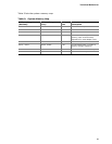
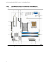
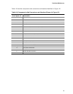
Table 10 lists the component-side connectors and headers identified in Figure 10.
Table 10. Component-side Connectors and Headers Shown in Figure 10
Item/callout
from Figure 10
Descri
ption
A PCI Conventional bus add-in card connector 1
B Front panel audio header
C PCI Conventional bus add-in card connector 2
D PCI Express x1 connector
E PCI Express x16 connector
F Processor core power connector (2 X 2)
G Rear chassis fan header
H Processor fan header
I Serial port header
J Main power connector (2 X 12)
K Diskette drive connector
L Chassis intrusion header
M Front chassis fan header
N Auxiliary front panel power LED header
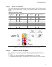
O Front panel header
P Serial ATA connectors [4]
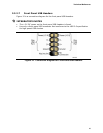
Q Front panel USB header
R Front panel USB header
S Front panel USB header
T Parallel ATA IDE connector
U IEEE 1394a header