


Technical Reference
45
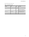
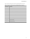
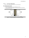
Table 16. Front Panel Audio Header
Pin Signal Name Pin Signal Name
1 [Port 1] Left channel 2 Ground
3 [Port 1] Right channel 4 PRESENCE# (Dongle present)
5 [Port 2] Right channel 6 [Port 1] SENSE_RETURN
7 SENSE_SEND (Jack detection) 8 Key (no pin)
9 [Port 2] Left channel 10 [Port 2] SENSE_RETURN
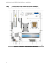
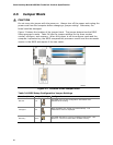
2.2.2.2 Add-in Card Connectors
The board has the following add-in card connectors:
• One PCI Express x16 connector supporting simultaneous transfer speeds up to
4 GBytes/sec of peak bandwidth per direction and up to 8 GBytes/sec concurrent
bandwidth.
• PCI Express x1: one PCI Express x1 connector. The x1 interface supports
simultaneous transfer speeds up to 250 Mbytes/sec of peak bandwidth per
direction and up to 500 MBytes/sec concurrent bandwidth.
• PCI Conventional (rev 2.3 compliant) bus: two PCI Conventional bus add-in card
connectors. The SMBus is routed to all PCI Conventional bus connectors. PCI
Conventional bus add-in cards with SMBus support can access sensor data and
other information residing on the board.
Note the following considerations for the PCI Conventional bus connectors:
• All of the PCI Conventional bus connectors are bus master capable.
• SMBus signals are routed to all PCI Conventional bus connectors. This enables PCI
Conventional bus add-in boards with SMBus support to access sensor data on the
board. The specific SMBus signals are as follows:
⎯ The SMBus clock line is connected to pin A40.
⎯ The SMBus data line is connected to pin A41.
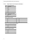
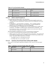
2.2.2.3 Auxiliary Front Panel Power/Sleep LED Header
Pins 1 and 3 of this header duplicate the signals on pins 2 and 4 of the front panel
header.
Table 17. Auxiliary Front Panel Power/Sleep LED Header
Pin Signal Name In/Out Description
1 HDR_BLNK_GRN Out Front panel green LED
2 Not connected
3 HDR_BLNK_YEL Out Front panel yellow LED