


Installation
Page 3-8
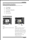
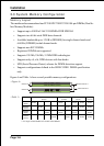
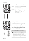
DIMM Module Installation
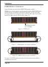
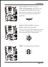
Figure 8 displays the notch on the DDR DIMM memory module.
DIMMs have 184 pins and one notch that matches with the DDR DIMM socket.
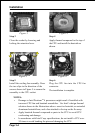
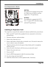
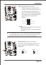
DIMM modules are installed by placing the chip firmly into the socket and
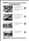
pressing straight down as shown in figure 9 until the white clips close and the
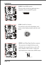
module fits tightly into the DIMM socket (figure 10).
Figure 8 - DIMM notch
Figure 10 - DIMM module clip after installation
To remove the DIMM module press down the white clips and the module is
released from the socket.
Figure 9 - DIMM module clips before installation
CENTER KEY ZONE
(2.5 V DRAM)