


Installation
Page 3-16
VCC
NC
GND
Key
GND
Data0-
Data1-
VCC
Data0+
Data1+
'
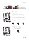
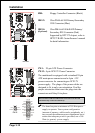
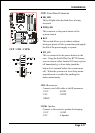
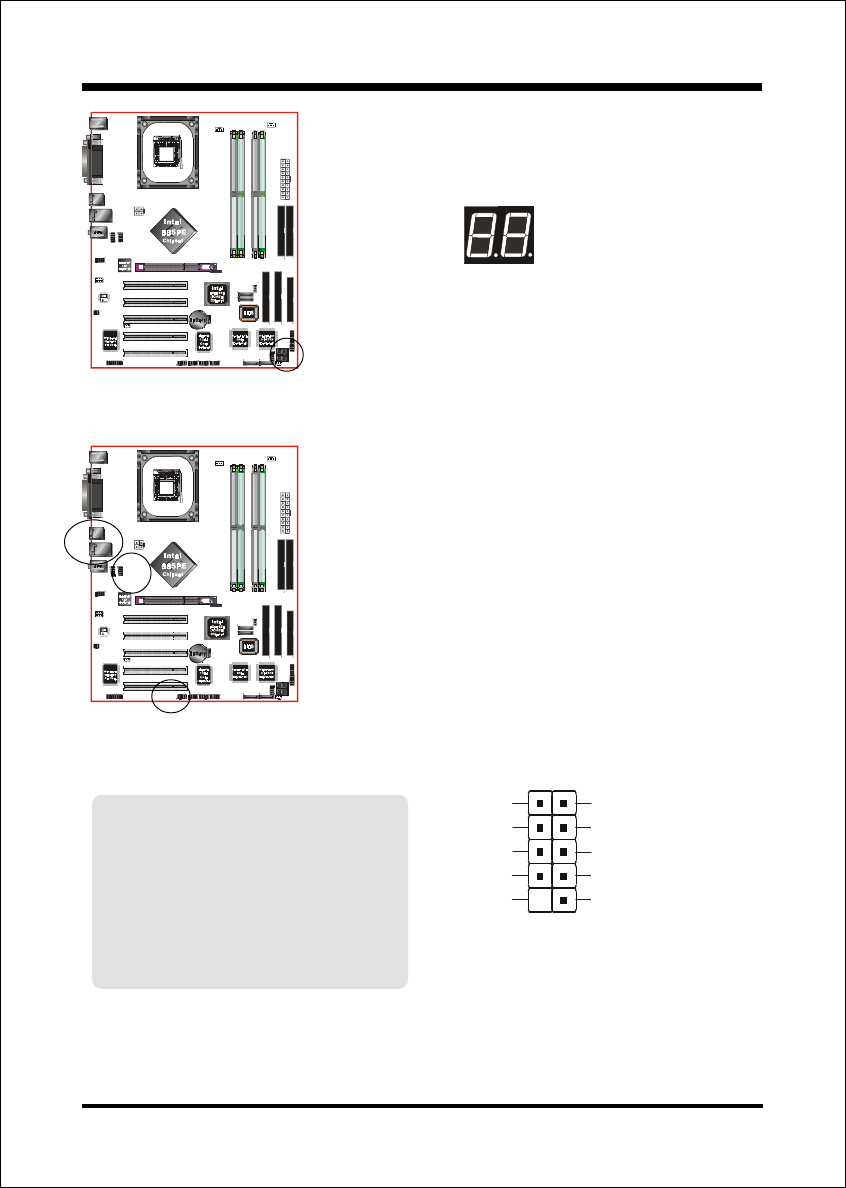
USB1/USB2/CUSB3/CUSB4: USB 2.0 ports
The mainboard is equipped with eight onboard
USB2.0/1.1 ports (4 at rear panel).
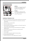
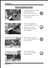
It is equipped with a 10-pin connector for connect-
ing 4 additional external USB 2.0/1.1 ports. If you
wish to use the additional USB ports, install the
card-edge bracket to the system chassis then insert
the connector that is attached to the USB port
cables to the 10-pin connector.
It will help your device more efficient for the transfer
speed up to 480Mbps.
USB3
USB1
USB2
USB4
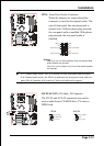
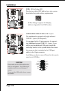
LED1: 80 Port Debug LED
Provides two digits LED light to show why system
boots failed for quick and easy optimization.
80 Port Debug 7-segment LED display
(Refer to Appendix E for POST codes)
CAUTION !
Please make sure the USB cable has the
same pin assignment. The different pin
assignment may be caused damage of
system.
If you need the USB cable, please contact
our retailer.