13
PIN
Description PIN
Description
17
GFPD8
18
GFPD9
19 GFPD10 20 GFPD11
21 GFPD12 22 GFPD13
23 GFPD14 24 GFPD15
25 GFPD16 26 GFPD17
27 GFPD18 28 GFPD19
29 GFPD20 30 GFPD21
31 GFPD22 32 GFPD23
33 N/C 34 N/C
35 SHFCLK 36 GFPVS
37 GFPDEN 38 GFPHS
39 GND 40 FPBKLP
41 N/C 42 N/C
43
N/C
44
N/C
1
2
44
43
N/C
GND
V
LCD
ENPVEE
GFPD0
GFPD2
GFPD4
GFPD6
GFPD8
GFPD10
GFPD12
GFPD14
GFPD16
GFPD18
GFPD20
N/C
GND
ENPVDD
GND
GFPD1
GFPD3
GFPD5
GFPD7
GFPD9
GFPD11
GFPD13
GFPD15
GFPD17
GFPD19
GFPD21
GFPD22
N/C
SHFCLK
GFPDEN
GND
N/C
N/C
GFPD23
N/C
GFPVS
GFPHS
FPBKLP
N/C
N/C
NOTE:
Please set the proper voltage of your panel using JP3 before
proceeding on installing it.
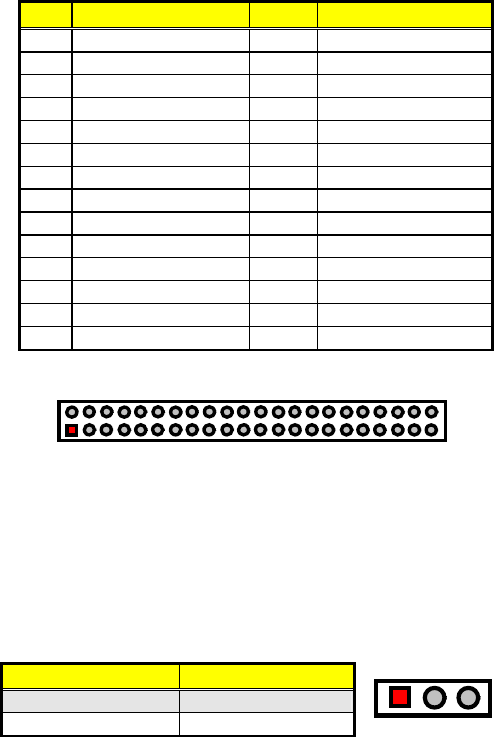
The HS-2606 has an onboard jumper that selects the working voltage
of the flat panel connected to the system. Jumper JP2 offers two
voltage settings for the user.
JP2: Panel Voltage Select
Options Settings
+3.3V (default) Short 1-2
+5V
Short 2-3
13


