


Installation
Page 3-11
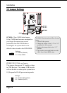
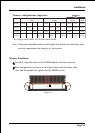
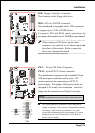
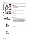
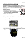
FDD: Floppy Controller Connector
This connects to the floppy disk drive.
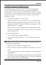
IDE1: ATA-66/100 IDE Connector
This mainboard is equipped with 1 IDE connectors
to support up to 2 ATA-100 IDE drives.
It supports PIO and DMA mode operations for
maximum data transfer rate of 100MB/sec per channel.
PW1
IDE1
FDD
PW12
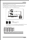
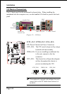
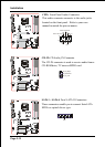
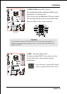
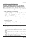
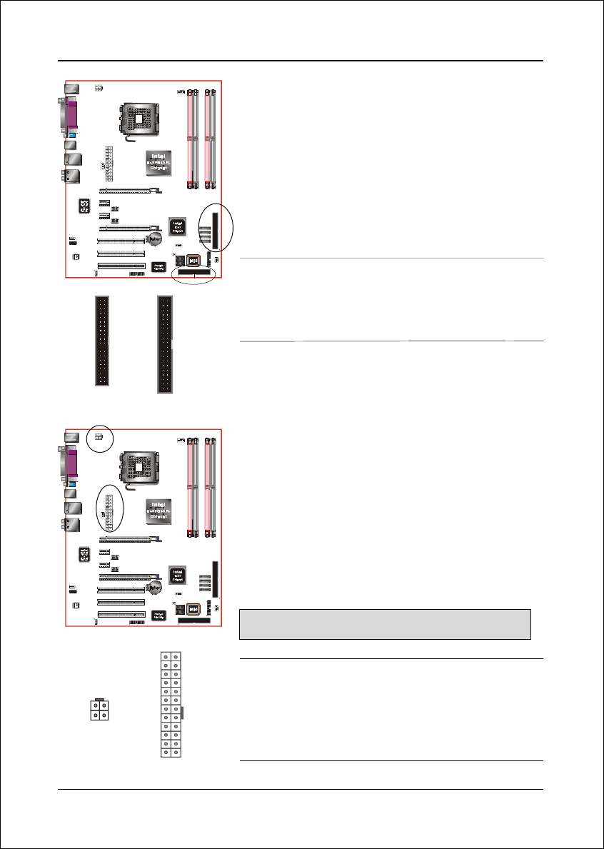
PW1: 24-pin ATX Power Connector
PW12: 4-pin ATX12V Power Connector
The mainboard is equipped with a standard 24-pin
ATX main power connector and a 4-pin +12V
power connector for connecting an ATX12V
power supply. The plugs of the power cables are
designed to fit in only one orientation. Insert the
plugs into the connectors until they fit in place.
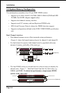
The board requires a minimum of 400 Watt power
supply to operate. Your system configuration (amount
of memory, add-in cards, peripherals, etc.) may
exceed this minimum power requirement. To ensure
adequate power, for GLI mode use a 550 Watt or
greater power supply.
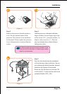
When using two IDE drives on the same
connector, one must be set to Master mode and
the other to Slave mode. Refer to your disk
drive user’s manual for details.
Caution:
The PW1 and PW12 Power Connector must be used simultaneously.
1
3
1
-12V3.3V
Ground+5V
PS-ON+5V
-5VPW-OK
+5V5VSB
+5V
+5V
Ground
+12V
+12V
3.3V
+12V+12V
23
11
4
2
3.3V3.3V
GroundGround
GroundGround
GroundGround
GroundGround
24
PW1
PW12
40 39
2
1
IDE1
34 33
2
1
FDD