


IXP1200 Network Processor Family ATM OC-3/12/Ethernet IP Router Example Design
Application Note 25
Modified on: 3/20/02,
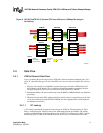
3.5.1 Ethernet Transmit Structure
The Ethernet Transmit microengine contains three fill threads and one transmit scheduler thread.
The Ethernet transmitter uses the eight even TIFO elements, allowing the ATM transmitter to use
the eight odd Transmit FIFO elements. This is the same TFIFO sharing mechanism that is used by
the L3fwd8_1f SDK example, except here the peer transmitter is ATM instead of Ethernet.
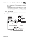
3.5.2 High Level Algorithm
As mentioned in “project_config.h”, defining ETHERNET_LOOPBACK allows the project to
forward packets from Ethernet source ports to Ethernet destination ports. Enabling this option adds
a small cost in the Ethernet transmitter because it needs to be able to handle transmit data starting
on variable buffer offsets.
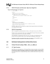
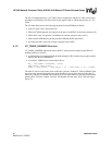
This implementation uses thread0 as a scheduler, and the others are used as fill threads:
Thread0:
while(1)
tx_100m_assign()
tx_100m_assign() makes work assignments to the three fill threads of this microengine. Slow ports
are mapped directly to TFIFO elements. Therefore, if the target port has no packets, the fill thread
is given a ‘skip’ assignment. When the fill thread executes a skip assignment, it forces the
hardware to skip a TFIFO element without transmitting any data from the TFIFO element onto the
IX bus.
Threads1,2,3:
while(1)
read assignment from scheduler
restore portinfo state from absolute registers
if (assigned to transmit a packet)
transfer MPKT to TFIFO and validate
update portinfo state
else
skip TFIFO element
endif
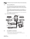
3.6 CRC-32 Calculations using IXP1240/1250 Hardware
The IXP1240 adds sdram_crc[] instructions to the IXP1200 instruction set for efficient CRC
calculation. This design takes advantage of that hardware support in the ATM receiver and the
ATM transmitter. On receive (reassembly), CRC is checked when ATM cells are transferred from
RFIFO to DRAM. On transmit (segmentation), CRC is generated when ATM cells are transferred
from DRAM to the TFIFO.
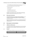
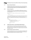
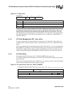
3.6.1 CRC-32 Hardware Checking on Receive
Quadword 0 is copied with an sdram_crc[r_fifo_rd], mask_right instruction. This applies the CRC
to the four bytes labeled "LLC0" in Figure 16, but not to the ATM header. The ATM header is not
actually needed in the DRAM data buffer, but it is transferred, because this is more efficient than
performing a read/modify/write to preserve insignificant bits in the buffer.