


LXD970A — Demo Board for 10/100 and 100BASE-FX Applications
12 Development Kit Manual
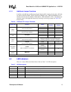
4.1.1 Function/Address Settings
The multi-function pins allow the user to enable or disable the applicable functions and determine
chip address according to the input level selected. Table 4 shows the status of the function
according to the (V
MF) selection.
Table 4. Hardware Control Interface (JP1) Functions
Address Input Voltage Levels
2
Pin Function VMF1VMF2VMF3VMF4
MF0
Address Bit 0 1 1 0 0
Auto-Negotiation
Sets the initial value of bit 0.12
Disabled
(0.12 = 0)
Enabled
(0.12 = 1)
Enabled
(0.12 = 1)
Disabled
(0.12 = 0)
MF1
Address Bit 1 1 1 0 0
Repeater / DTE Mode
Sets the initial value of bit 19.13
DTE
(19.13 = 0)
Repeater
(19.13 = 1)
Repeater
(19.13 = 1)
DTE
(19.13 = 0)
MF2
Address Bit 2 1 1 0 0
Nibble (4B) / Symbol (5B) Mode
Sets the initial value of bit 19.4
Nibble (4B)
(19.4 = 0)
Symbol (5B)
(19.4 = 1)
Symbol (5B)
(19.4 = 1)
Nibble (4B)
(19.4 = 0)
MF3
Address Bit 3 1 1 0 0
Scrambler Operation
Sets the initial value of bit 19.3
Enabled
(19.3 = 0)
Bypassed
(19.3 = 1)
Bypassed
(19.3 = 1)
Enabled
(19.3 = 0)
MF4
Address Bit 4 1 1 0 0
If Auto-Negotiate Enabled via MF0, MF4 works in combination with MAN2 (CFG1) to control
operating speed advertisement capabilities. See Table 5 for details.
If Auto-Negotiate Disabled
Then TX/F Mode
Sets the initial value of bit 19.2
100TX
(19.2 = 0)
100FX
(19.2 = 1)
100FX
(19.2 = 1)
100TX
(19.2 = 0)
Table 5. Operating Speed Advertisement Settings
MF4 Input
Voltage Levels
1
MAN2
(CFG1)
Function
If Auto-Negotiate Enabled via MF0
V
MF1, VMF4 Jumper Not Installed Advertise all capabilities, Ignore MAN1 (FDE)
V
MF1, VMF4 Jumper Installed Advertise 10 Mbps only, Follow MAN1 (FDE)
V
MF2, VMF3 Jumper Not Installed Advertise 100 Mbps only, Follow MAN1 (FDE)
V
MF2, VMF3 Jumper Installed Advertise 10/100 Mbps, Follow MAN1 (FDE)
1. Input Voltage Levels (V
MF1, VMF2, VMF3, VMF4) for MF pins.