


LXD970A Demo Board for 10/100 and 100BASE-FX Applications Development Kit Manual iii
Contents
1.0 General Description ..................................................................................................5
1.1 Features ................................................................................................................5
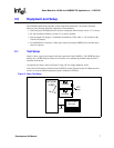
2.0 Equipment and Setup...............................................................................................7
2.1 Test Setup.............................................................................................................7
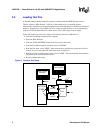
2.2 Loading Test File...................................................................................................7
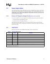
2.3 Power Supply Option.............................................................................................8
2.3.1 External +5V Supply for Analog Circuitry (VCCA, VCCT and VCCR)..9
2.4 Test Points ............................................................................................................9
3.0 Jumpers .......................................................................................................................10
4.0 Hardware Control Interface..................................................................................11
4.1 Multi-Function Pins..............................................................................................11
4.1.1 Function/Address Settings .................................................................11
4.1.2 Additional Jumper Functions ..............................................................12
4.2 LED Indicators.....................................................................................................13
Figures
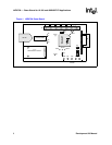
1 LXD970A Demo Board..........................................................................................6
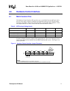
2 Basic Test Setup ...................................................................................................7
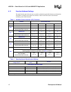
3 Optional Test Setup..............................................................................................8
4 Hardware Control Interface Jumper Placement .................................................11
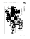
5 LXD970A Schematic ...........................................................................................14
Tables
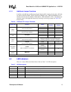
1 Test Point Descriptions .........................................................................................9
2 Jumper Descriptions............................................................................................10
3 MF Pins Input Voltage Levels..............................................................................11
4 Hardware Control Interface (JP1) Functions.......................................................12
5 Operating Speed Advertisement Settings ...........................................................12
6 Additional JP1 Jumper Functions........................................................................13
7 LED Descriptions.................................................................................................13