


Intel
®
LXD972M Transceiver Demo Board (Board Rev A1)
Preliminary User’s Guide 11
Document Number: 303125
Revision Number: 002
Revision Date: October 22, 2004
2.4 Configurations
2.4.1 Optional Test Setup, Using Two Intel
®
LXD972M Demo Boards
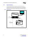
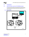
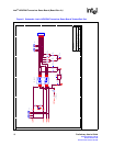
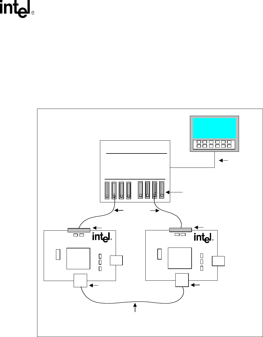
Figure 3 shows an optional test setup using two LXD972M Demo Boards. Each Demo Board plugs
into a SmartBits Advanced Performance Test Box through standard 40-pin MII cables. The two
LXD972M Demo Boards are linked through a Twisted-Pair crossover cable connected to the RJ-45
jack on each board. Operation can be set for evaluation of 10 Mbps, 100 Mbps, and auto-
negotiation capabilities.
Figure 3. Optional Test Setup
RS-232
Twisted-Pair
Crossover
Cable
SmartBits
Advanced Multi-port
Performance
Tester
MII
Cards
Computer with
Smart Windows
MII Cable
RJ-45
MII
Connector
LXT972M
LXD972M
RJ-45
MII
Connector
LXT972M
LXD972M
B3572-05