


Intel
®
LXD972M Transceiver Demo Board (Board Rev A1)
Preliminary User’s Guide 19
Document Number: 303125
Revision Number: 002
Revision Date: October 22, 2004
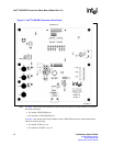
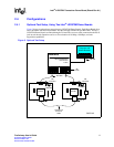
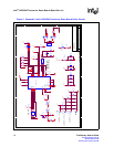
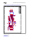
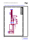
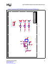
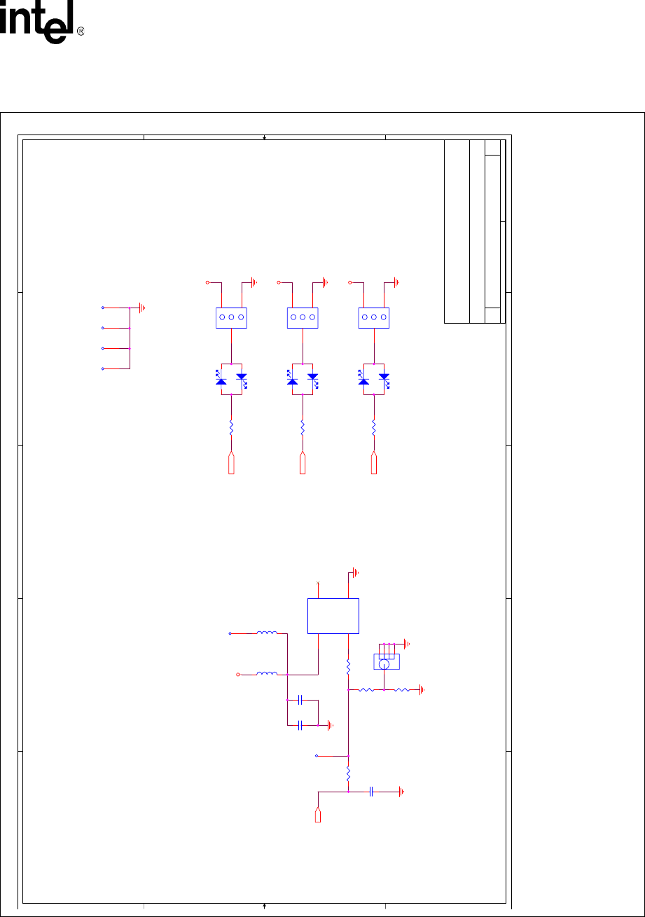
Figure 7. Schematic: Intel
®
LXD972M Transceiver Demo Board Configuration
A
A
B
B
C
C
D
D
E
E
4 4
3 3
2 2
1 1
DISTRIBUTE, LABEL AS "GND"
LED1
X=DO NOT INSTALL
LED2
CFG
Intel(R) LXD972M Transceiver CAPS, LED CONFIG., MISC. A1
LXD972M LQFP48C DV/DEMO
Intel Corporation
9750 Goethe Road
Sacramento, CA 95827
B
55Monday, September 20, 2004
Title
Size Document Number Rev
Date: Sheet
of
VCCX
LED/CFG1
LED/CFG2
LED/CFG3
GND
VCCIO
GND
VCCIO
GND
VCCIO
GND
GND
GND
VCC
GND
GND
GND
C37
20pF
D6
LED
J3 SMB
1
2
3
4
5
R76
50 1%
D3
LED
TP37
1
TP2
1
C16
0.1uF
JP2
HEADER 3 PIN
1
2
3
D5
LED
TP3
1
R2
180
C50
0.1uF
JP3
HEADER 3 PIN
1
2
3
FB6
X
D8
LED
FB3
FERRITE
D4
LED
TP38
1
R3
180
TP5
1
R75
X
D7
LED
JP1
HEADER 3 PIN
1
2
3
R70
50 1%
R1
180
Y2
25MHzCRYSTAL OSC
1
78
14
NC
GNDOUT
VCC
TP4
1
R74
0
XIN