MIC-3358 User’s Manual 28
2.6 USB Connector (CN5/6 and Rear I/O)
The MIC-3358 provides two USB (Universal Serial Bus) 2.0 channels
either via two front USB ports (CN5 and CN6) in MIC-3358 or via J5
connector to one USB connector (CN8) in real transition board. The USB
interface gives complete plug and play, hot attach/detach for up to 127
external devices. The MIC-3358 USB interface complies with USB spec-
ification rev. 2.0 and is polyswitch protected. The USB interface can be
disabled in the system BIOS setup. The USB controller default is
"Enabled" but the USB keyboard support default is "Disabled".
2.7 PMC Connector (J11, J12, J14)
The MIC-3358 supports one PMC (PMC Mezzanine Card) modules on
PCI bus. This 32-bit, 3.3/5 V(I/O) PCI bus is available at connectors J11
and J12. J14 is applied for user definitions. Front panel access is provided
for the PMC interface.
2.8 CompactFlash™ Socket (CN2)
CompactFlash™ is a standard form factor for mass storage and I/O cards.
Based on the PCMCIA Standard, CompactFlash™ cards are approxi-
mately 1/4 the volume of a PC Card. In order to achieve the small size,
the interface pin count is 50-pins compared to the PCMCIA's 68-pin.
The MIC-3358 supports one CompactFlash™ socket in CN2 connector. It
helps file and data storage in the CompactFlash™ card rather than the tra-
ditional hard drive.
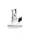
2.9 Card Installation
The CompactPCI™ connectors are firm and rigid, and require careful
handling while plugging and unplugging. Improper installation of a card
can easily damage the backplane of the chassis. The inject/eject handles


