


20 SBC-455 User's Manual
Floppy drive connections (FLOPPY DISK)
You can attach up to two floppy disks to the SBC-455's on-board
controller. You can use any combination of 5 1/4" (360 KB and
1.2 MB) and/or 3 1/2" (720 KB, 1.44 MB, and 2.88 MB) drives.
The SBC-455 CPU card comes with a 34-pin daisy-chain drive
connector cable. On one end of the cable is a 34-pin flat-cable
connector. There are two sets of floppy disk drive connectors, one
in the middle, and one on the other end. Each set consists of a 34-
pin flat-cable connector (usually used for 3.5" drives) and a
printed-circuit board connector (usually used for 5.25" drives).
Connecting the floppy drive
1. Plug the 34-pin flat-cable connector into the FLOPPY DISK
connector.
2. Attach the appropriate connector on the other end of the cable
to the floppy drive(s). You can use only one connector in the
set. The set on the end (after the twist in the cable) connects to
the A: floppy. The set in the middle connects to the B: floppy.
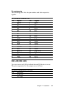
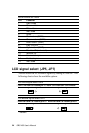
Pin assignments
The following table lists the pin assignments for the FLOPPY
DISK connector:
FLOPPY DISK Connector
Pin Signal Pin Signal
1~33 (odd) GND 2 High density
4, 6 Unused 8 Index
10 Motor enable A 12 Driver select B
14 Driver select A 16 Motor enable B
18 Direction 20 Step pulse
22 Write data 24 Write enable
26 Track 0 28 Write protect
30 Read data 32 Select head
34 Disk change