


30 SBC-455 User's Manual
External switches and LEDs
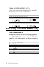
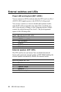
Power LED and keylock (KEY LOCK)
You can connect an LED to indicate when the CPU card is on. Pin 1
of KEY LOCK supplies power to the LED; Pin 3 is the ground.
You can use a switch (or a lock) to disable the keyboard. In this
state the PC will not respond to any input. This is useful if you
don’t want anyone to change or stop a running program. Simply
connect the switch between Pins 4 and 5. The pin assignments
appear in the following table:
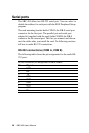
Power LED and keylock (KEY LOCK)
Pin Function
1 LED Power (+5 V)
2 No Connector
3 Ground
4 Keyboard lock
5 Ground
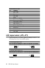
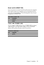
External speaker (EXT SPK)
The CPU card has its own buzzer. You can disable the internal
buzzer and connect an external speaker to EXT SPK. Enabling the
external speaker automatically disables the internal buzzer.
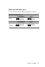
External speaker (EXT SPK)
Pin Function
1 Vcc
2 Speaker output
3 Buzzer in
4 Speaker output