


Description 11
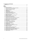
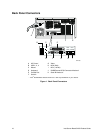
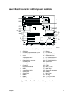
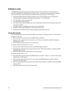
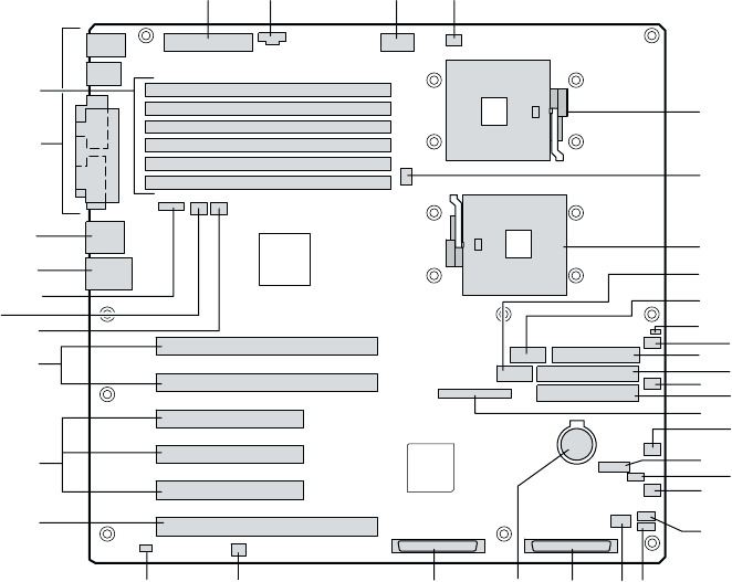
Server Board Connector and Component Locations
A
B
C
D
E
F
G
H
I
J
K
L
M
N
O
P
Q
RSTUVX
W
Y
Z
AA
BB
CC
DD
EE
FF
GG
HH
II JJ KK
LL
OM14357
A Primary Processor Socket (CPU1) T LVD SCSI B
B CPU2 Fan U Battery
C Secondary Processor Socket (CPU2) V LVD SCSI A
D Front Panel USB W Jumper block CN53
E Serial B X Chassis Intrusion
F Jumper Block CN27 Y PCI-X 64-bit/133 MHz
G System Fan 5 Z PCI 32-bit/33 MHz
H Floppy disk drive connector AA PCI-X 64-bit/100 MHz
I Secondary IDE BB System Fan 1
J System Fan 6 CC System Fan 2
K Primary IDE DD ICMB
L Front Panel connector EE NIC1 (10/100)
M IPMB FF NIC2 (Gbit)
N Jumper Block CN43 GG System I/O connectors
O System Fan 3 HH DIMMs
P System Fan 4 II Main Power
Q HSBP B JJ Aux Sig
R HSBP A KK +12 V CPU Power
S HDD LED Connector LL CPU1 Fan
Figure 2. Server Board Connector and Component Locations