


TFX12V Power Supply Design Guide
Thin Form Factor with 12 V Connector
Version 2.0
16
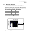
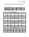
Table 6: Typical Power Distribution for 270 W SFX12V Configurations
Output Minimum
Current
(amps)
Maximum
Current
(amps)
Peak
Current
(amps)
+12 V1DC
1.0 7.0 9.0
+12 V2DC
1.0 13.0
+5 VDC
0.3 18.0
+3.3 VDC
0.5 17.0
-12 VDC
0.0 0.3
+5 VSB
0.0 2.0 2.5
Note: Total combined output of 3.3 V and 5 V is 20 W
Peak currents may last up to 17 seconds with not more than one occurrence per minute
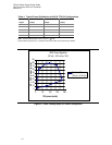
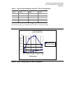
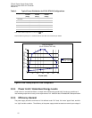
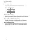
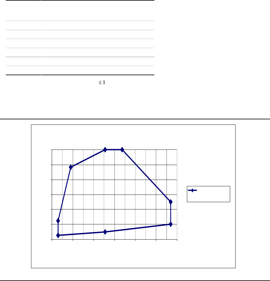
270W Cross Regulation
(5V rail + 3.3V rail vs. 12V1 +12V2)
0
20
40
60
80
100
120
0 40 80 120 160 200 240
12V power (watts)
5V + 3.3V
p
ower
(
watts
)
Combined Power
(5V rail + 3.3V rail)
Figure 5 Cross Loading Graph for 270W Configuration
2.2.4 Power Limit / Hazardous Energy Levels
Under normal or overload conditions, no output shall continuously provide 240 VA under any conditions of
load including output short circuit, per the requirement of UL 1950/CSA 950 / EN 60950/IEC 950 specification.
2.2.5 Efficiency General
The power supply should be a minimum of 70% efficient under “Full” load, 70% under “typical” load, and 60%
in a “light” load idle condition. The efficiency of the power supply should be tested at nominal input voltage of