


TFX12V Power Supply Design Guide
Thin Form Factor with 12 V Connector
Version 2.0
6
Figures
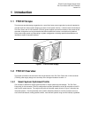
Figure 1. TFX12V Power Supply...................................................................................................... 7
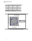
Figure 2. Cross Loading Graph for 180W Configuration................................................................. 13
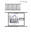
Figure 3. Cross Loading Graph for 220W Configuration................................................................. 14
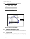
Figure 4. Cross Loading Graph for 240W Configuration................................................................. 15
Figure 5 Cross Loading Graph for 270W Configuration................................................................. 16
Figure 6. Differential Noise Test Setup.......................................................................................... 19
Figure 7. Power Supply Timing ..................................................................................................... 21
Figure 8. PS_ON# Signal Characteristics...................................................................................... 23
Figure 9. Power Supply Dimensions and Recommended Feature Placements (not to scale) ....... 27
Figure 10. Power Supply Mounting Slot Detail ............................................................................... 28
Figure 11. Fan Right and Fan Left Orientations of Power Supply in a Chassis .............................. 29
Figure 12. Suggested TFX12V Chassis Cutout.............................................................................. 30
Figure 13. Suggested Mounting Tab (chassis feature)................................................................... 30
Figure 14. TFX12V Connectors (Pin-side view, not to scale) ......................................................... 32
Figure 15. Serial ATA Connector 34
Tables
Table 1. AC Input Line Requirements........................................................................................... 10
Table 2. DC Output Voltage Regulation........................................................................................ 12
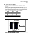
Table 3. Typical Power Distribution for 180 W TFX12V Configurations......................................... 13
Table 4. Typical Power Distribution for 220 W TFX12V Configurations......................................... 14
Table 5. Typical Power Distribution for 240 W TFX12V Configurations......................................... 15
Table 6: Typical Power Distribution for 270 W SFX12V Configurations ........................................ 16
Table 7: Efficiency Vs Load .......................................................................................................... 17
Table 8. Loading Table for Efficiency Measurements ................................................................... 17
Table 9. Energy Star Input Power Consumption........................................................................... 18
Table 10. DC Output Noise/Ripple.................................................................................................. 18
Table 11. DC Output Transient Step Sizes..................................................................................... 19
Table 12. Output Capacitive Loads................................................................................................. 20
Table 13. PWR_OK Signal Characteristics..................................................................................... 22
Table 14. PS_ON# Signal Characteristics ...................................................................................... 23
Table 15. Over Voltage Protection.................................................................................................. 25
Table 16. Harmonic Limits, Class D Equipment.............................................................................. 39