TFX12V Power Supply Design Guide
Thin Form Factor with 12-V Connector
Version 2.0
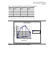
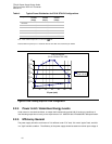
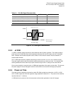
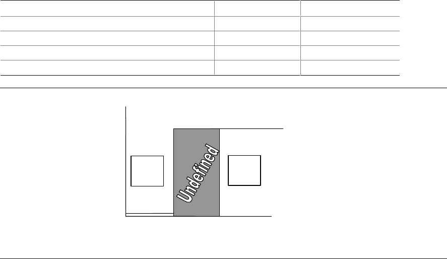
Table 14. PS_ON# Signal Characteristics
Parameter Minimum Maximum
V
IL
, Input Low Voltage 0.0 V 0.8 V
I
IL
, Input Low Current (Vin = 0.4 V) -1.6 mA
V
IH
, Input High Voltage (Iin = -200 µA) 2.0 V
V
IH
open circuit, Iin = 0 5.25 V
Enable
Disable
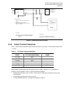
PS_ON# Voltage
0.8 2.0
5.25 = Maximum Open-
Circuit Voltage
≥ 2.0 V
PS is
disabled
≤
0.8 V
PS is
enabled
Hysteresis
≥
0.3 V
Figure 8. PS_ON# Signal Characteristics
2.3.3 +5 VSB
+5 VSB is a standby supply output that is active whenever the AC power is present. This output provides a
power source for circuits that must remain operational when the five main DC output rails are in a disabled
state. Example uses include soft power control, Wake on LAN, wake-on-modem, intrusion detection, or
suspend state activities.
The +5 VSB output should be capable of delivering a minimum of 2.0 A. at +5 V ± 5% to external circuits.
The power supply must be able to provide the required power during a "wake up" event. If an external USB
device generates the event, there may be peak currents as high as 2.5 A., lasting no more than 500 ms.
Over current protection is required on the +5 VSB output regardless of the output current rating. This ensures
the power supply will not be damaged if external circuits draw more current than the supply can provide.
2.3.4 Power-on Time
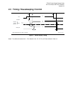
The power-on time is defined as the time from when PS_ON# is pulled low to when the +12 VDC, +5 VDC,
and +3.3 VDC outputs are within the regulation ranges specified in Section 2.2.1. The power-on time shall be
less than 500 ms (T
1
< 500 ms).
+5 VSB shall have a power-on time of two seconds maximum after application of valid AC voltages.


