


English
7
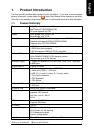
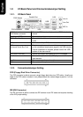
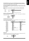
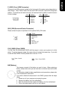
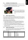
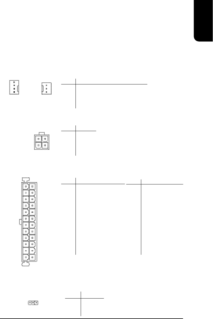
CPU_FAN (CPU Fan Power Connector); SYS_FAN (System Fan Power Connector)
The cooler fan power connector supplies a +12V power voltage via a 3-pin/4-pin(only for CPU_FAN)
power connector and possesses a ful-proof connection design.
Most coolers are designed with color-coded power connector wires. A red power connector wire indi-
cates a positive connection and requires a +12V power voltage. The black connector wire is the
ground wire (GND).
Please remember to connect the power to the cooler to prevent system overheating and failure.
Caution!
Please remember to connect the power to the CPU fan to prevent CPU overheating and failure.
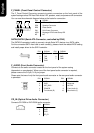
ATX_12V (+12V Power Connector)
The ATX_12V power connector provides power to the CPU. If this connector is not Attached,
the system will not start.
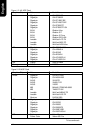
1
CPU_FAN
SYS_FAN
PIN SIGNAL
1 GND
2 GND
3 +12V
4 +12V
PIN SIGNAL
1 GND
2 +12V
3 Sense
4 Speed Control (Only for CPU_FAN)
1
3
1
4
2
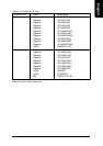
PIN SIGNAL
1 3.3V
2 3.3V
3 GND
4 +5V
5 GND
6 +5V
7 GND
8 Power Good
9 5V SB (stand by +5V)
10 +12V
11 +12V
12 3.3V (only for 24-pin ATX)
PIN SIGNAL
13 3.3V
14 -12V
15 GND
16 PS_ON (soft on/off)
17 GND
18 GND
19 GND
20 -5V
21 +5V
22 +5V
23 +5V
24 GND
PWR_LED
Connects to the system power LED indicator whereby the power is indicated as ON or OFF.
However, the indicator will flash when the system is suspended.
PIN SIGNAL
1 MPD+
2 MPD-
3 MPD-
1
13 1
24 12
ATX (ATX Power Connector)
The ATX power connector provides power to the motherboard. Prior to connection, please
make sure that the power supply is disconnected.