


English
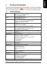
9
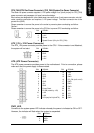
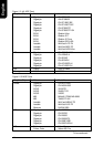
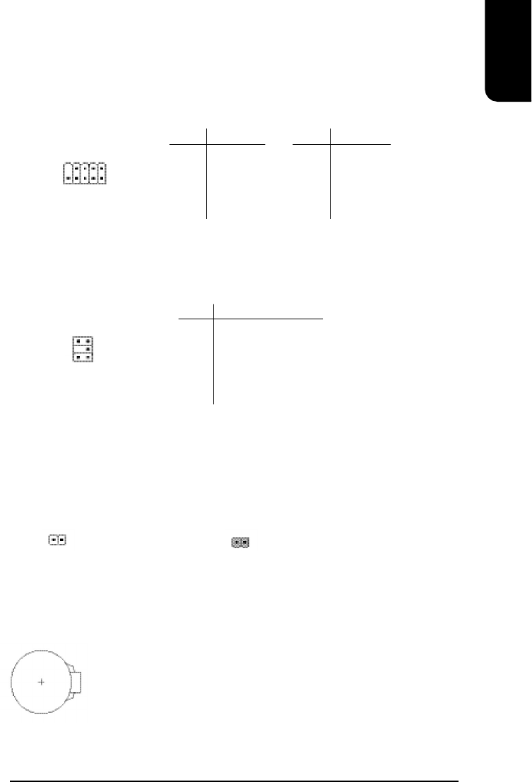
F_USB1 (Front USB Connector)
Connects to the USB connector located on the front panel of the system casing (dependent on
case design). Note: Please make sure that each USB connection matches its designated
position. If connections are made incorrectly, the result can lead to inability to use the function
or even damage.
PIN SIGNAL
6 USB Dy+
7 GND
8 GND
9 NO PIN
10 NC
PIN SIGNAL
1 POWER
2 POWER
3 USB Dx-
4 USB Dy-
5 USB Dx+
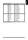
SUR_CEN (Surround Center Connector)
Please contact the place of purchase for the optional SUR_CEN cable.
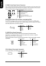
CLR_CMOS (Clear CMOS)
You can clear the motherboard CMOS with the jumper to return your system to its initial
status. To prevent improper usage, the jumper does not include the jumper plug. If you wish
to use the Clear CMOS function, please short circuit the 1-2 Pin.
Short : Clear CMOS
1
Open : Normal
1
The improper removal of the battery can result in harm. When replacing a
battery, please make sure you use one that is of similar brand and model
number.
For information related to battery specifications and precautions, please refer
to the manufacturer instructions.
If you wish to delete the data stored in the CMOS, please follow the steps
below:
1. Please turn off your computer and unplug the power.
2. Remove the battery from the motherboard.
3. Wait 10 minutes and then replace the battery onto the motherboard.
4. Plug in the power supply and turn on your system.
BAT(Battery)
6 5
12
PIN SIGNAL
1 SUR OUTL
2 SUR OUTR
3 GND
4 No Pin
5 CENTER_OUT
6 BASS_OUT
210
19