


8
English
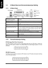
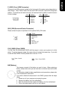
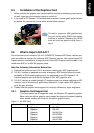
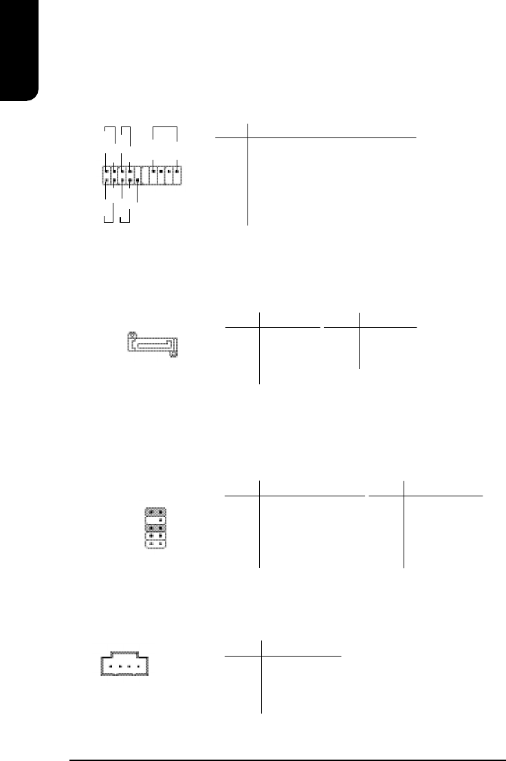
F_AUDIO (Front Audio Connector)
Connects to the audio connector located on the front panel of the system casing
(dependent on case design). When use of the front panel audio connector is required,
please remove the 5-6 pin, 9-10 pin jumper.
Please note that use of only the front panel audio connector or the rear panel audio connector
is permitted.
PIN SIGNAL
1 MIC
2 GND
3 MIC_BIAS
4 POWER
5 Front Audio (R)
PIN SIGNAL
6 Rear Audio (R)
7 Reserved
8 NO PIN
9 Front Audio (L)
10 Rear Audio (L)
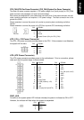
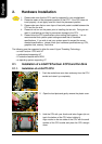
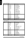
SATA0/SATA2 (Serial ATA Connector, controlled by ICH6)
The SATA0/2 connector is able to connect a single Serial ATA device via a SATA cable.
For the connected SATA hard disk to work correctly, please check the related BIOS setting
and install proper driver for the SATA controller.
PIN SIGNAL
5 RXN
6 RXP
7 GND
PIN SIGNAL
1 GND
2 TXP
3 TXN
4 GND
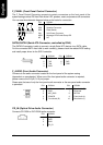
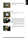
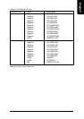
F_PANEL (Front Panel Control Connector)
The F_Panel Control Connector connects to certain connectors on the front panel of the
system casing such as IDE Hard Disk Active LED, speaker, reset, and power on/off connectors.
You can use the schematic diagram below as the basis for connection.
PIN SIGNAL
HD IDE Hard Disk Active LED
SPK Speaker Connector
RES Reset Switch
PW Soft Power Connector
MSG Message LED/Power/Sleep LED
NC NC
1
2
19
20
HD-
HD+
RES+
RES-
NC
SPK-
MSG-
MSG+
PW-
PW+
SPK+
10
2 1
9
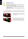
CD_IN (Optical Drive Audio Connector)
Connects CD-ROM or DVD-ROM audio connector.
PIN SIGNAL
1 CD_L
2 GND
3 GND
4 CD_R
1
7
1