


EasyLAN Wireless Interface Kit Installation Instructions 9
Chapter 2 — Physical Installation
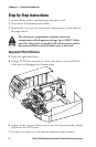
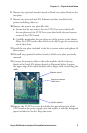
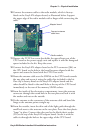
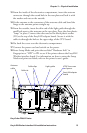
Connect the antenna cable to the radio module, which is factory-
fitted on the EasyLAN adapter board, as illustrated below. Support
the upper edge of the radio module with a finger while connecting the
cable.
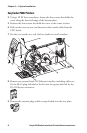
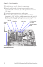
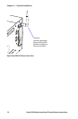
Remove the #T20 Torx screw that holds the upper/front part of the
CPU board to the power supply unit and replace it with the hexagonal
spacer included in the kit. Keep the screw.
Connect the EasyLAN adapter board to the PCI connector (J84) on
the CPU board so the hole in the board becomes aligned with the
spacer and secure the board with the #T20 Torx screw.
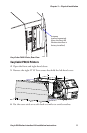
Route the antenna cable over the SIMMs on the CPU board towards
the rear plate and secure it using the cable clips included in the kit.
One clip is factory-fitted on the EasyLAN adapter board and the
other should be fitted in the small hole at the top of the CPU board
immediately to the rear of the memory SIMM sockets.
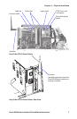
From the inside of the electronics compartment, insert the antenna
connector through the round hole in the rear plate and lock it with
the washer and nut on the outside.
Fit the antenna to the connector of the antenna cable and bend the
hinge so the antenna points straight up.
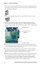
From the outside, insert the thin end of the light guide through the
small hole next to the antenna on the rear plate. Press the clear plastic
“lamp” in place. Connect the other end to the black plastic socket
(D1) at the top of the EasyLAN adapter board. Secure it with the
cable tie through the hole at the upper edge of the CPU board.
10
11
12
13
14
15
16
Radio module
Adapter board
Connect antenna
cable here