


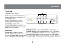
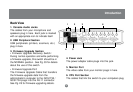
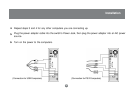
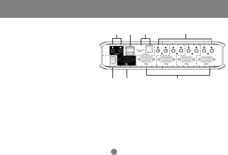
Back View
1. Console Audio Jacks
The cables from your microphone and
speakers plug in here. Each jack is marked
with an appropriate icon to indicate itself.
2. USB Peripheral Section
USB peripherals (printers, scanners, etc.)
plug in here.
3. Firmware Upgrade Section
• Firmware Upgrade Recovery Switch:
During normal operation and while performing
a firmware upgrade, this switch should be in
the NORMAL position. See Pg. 33 for details
about the use of this switch.
• Firmware Upgrade Port:
The Firmware Upgrade Cable that transfers
the firmware upgrade data from the
administrator’s computer to the GCS1732 /
GCS1734 plugs into this RJ-11 connector.
See Pg. 25 for firmware upgrading details.
4. Power Jack
The power adapter cable plugs into this jack.
5. Monitor Port
The video cable from your monitor plugs in here.
6. CPU Port Section
The cables that link the switch to your computers plug
1
2
36
654
8
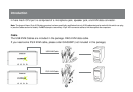
Introduction