


1616
1616
16
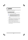
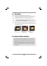
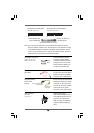
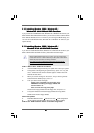
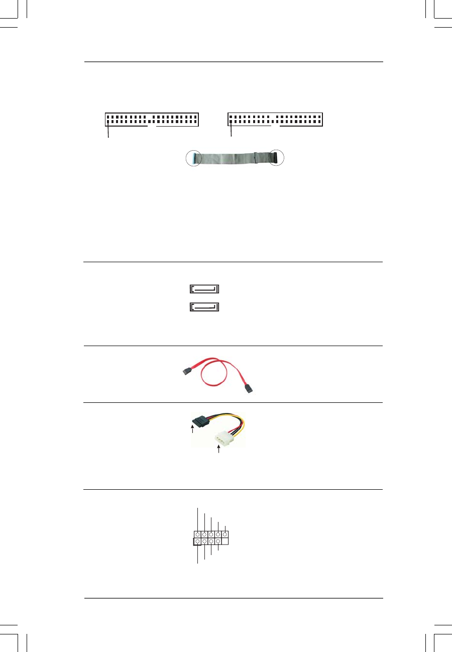
IDE1
PIN1
IDE2
PIN1
connect the black end
to the IDE devices
connect the blue end
to the motherboard
80-conductor ATA 66/100/133 cable
Primary IDE Connector (Blue) Secondary IDE Connector (Black)
(39-pin IDE1, see p.9 No. 7) (39-pin IDE2, see p.9 No. 6)
Note: If you use only one IDE device on this motherboard, please set the IDE
device as “Master”. Please refer to the instruction of your IDE device vendor
for the details. Besides, to optimize compatibility and performance, please
connect your hard disk drive to the primary IDE connector (IDE1, blue) and
CD-ROM to the secondary IDE connector (IDE2, black).
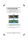
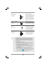
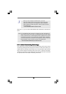
Serial ATA II Connectors These Serial ATA II (SATA II)
(SATA II_1: see p.9, No. 13) connectors support SATA II
(SATA II_2: see p.9, No. 12) or SATA hard disk for internal
storage devices. The current
SATA II interface allows up to
3.0 Gb/s data transfer rate.
Serial ATA (SATA) Either end of the SATA data cable
Data Cable can be connected to the SATA /
SATAII hard disk or the SATAII
connector on the motherboard.
SATA2
SATA1
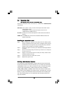
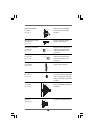
Serial ATA (SATA) Please connect the black end of
Power Cable SATA power cable to the power
(Optional) connector on each drive. Then
connect the white end of SATA
power cable to the power
connector of the power supply.
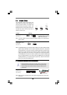
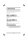
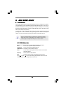
USB 2.0 Header HD 8CH I/O accommo-
(9-pin USB67) dates 4 default USB 2.0 ports. If
(see p.9 No. 17) those USB 2.0 ports on the I/O
panel are not sufficient, this
USB 2.0 header is available to
support 2 additional USB 2.0
ports.
connect to the SATA HDD
power connector
connect to the
power supply
USB_P WR
USB_P WR
P +7
P-7
P +6
P-6
GND
GND
DUMMY
1