


1818
1818
18
MID I_OUT
JAB2
JBY
JBB2
MID I_IN
+5V
JAY
GND
GND
1
JAX
JAB1
+5V
JBX
JBB1
+5V
+5V
DUMMY
DUMMY
S PEAKER
1
GND
PWRBTN#
PLED-
PLED +
DUMMY
RES ET#
GND
HDLED+
HDLED-
1
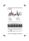
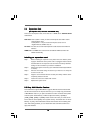
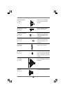
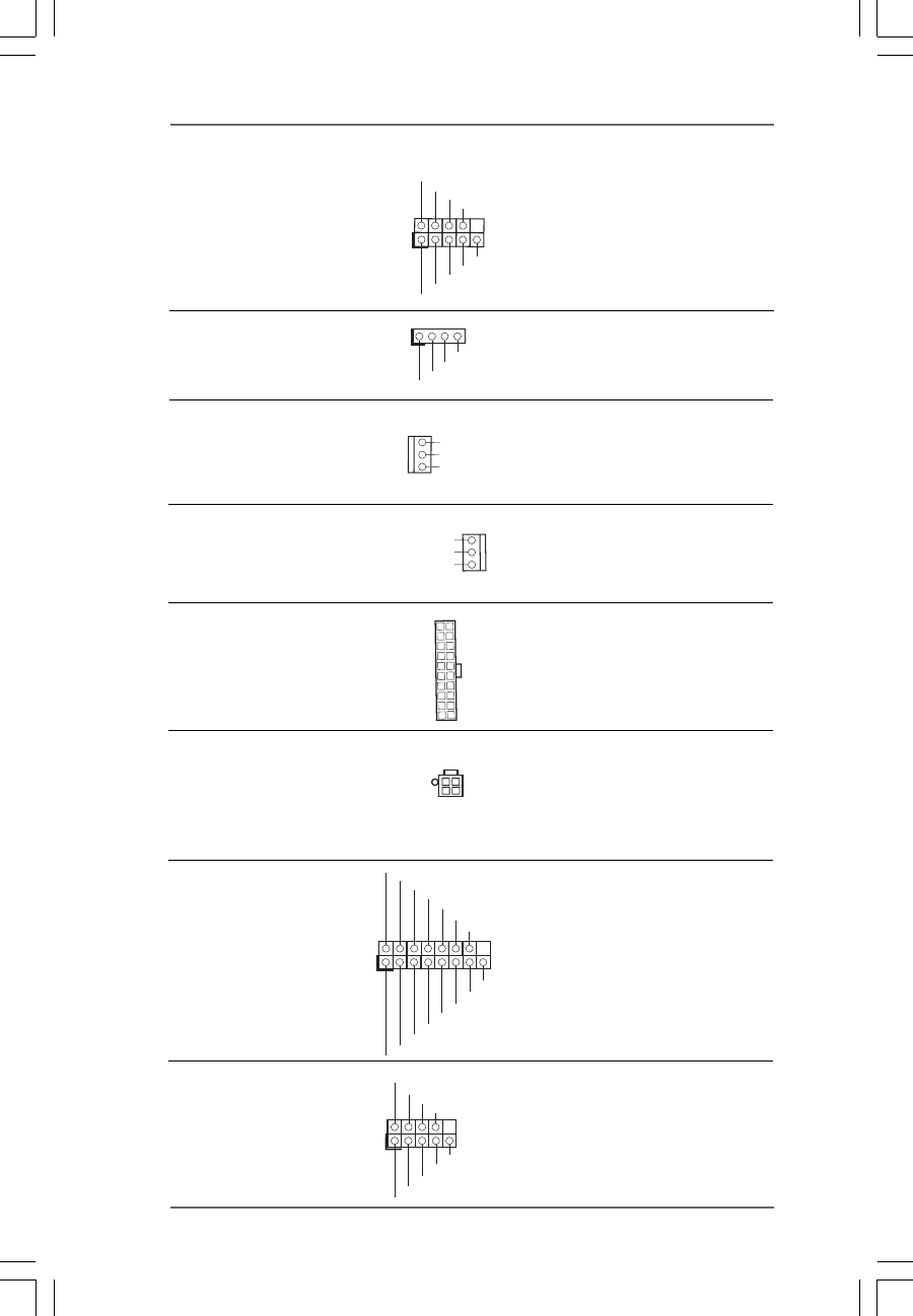
System Panel Header This header accommodates
(9-pin PANEL1) several system front panel
(see p.9 No. 15) functions.
Chassis Speaker Header Please connect the chassis
(4-pin SPEAKER 1) speaker to this header.
(see p.9 No. 16)
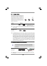
Chassis Fan Connector Please connect a chassis fan
(3-pin CHA_FAN1) cable to this connector and
(see p.9 No. 14) match the black wire to the
ground pin.
CPU Fan Connector Please connect the CPU fan
(3-pin CPU_FAN1) cable to this connector and
(see p.9 No. 30) match the black wire to the
ground pin.
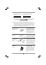
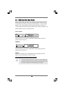
ATX Power Connector Please connect an ATX power
(20-pin ATXPWR1) supply to this connector.
(see p.9 No. 28)
ATX 12V Power Connector Please note that it is necessary
(4-pin ATX12V1) to connect a power supply with
(see p.9 No. 2) ATX 12V plug to this connector.
Failing to do so will cause power
up failure.
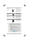
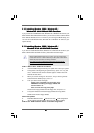
Game Port Header Connect a Game cable to this
(15-pin GAME1) header if the Game port bracket
(see p.9 No. 22) is installed.
Serial port connector This COM1 connector
(9-pin COM1) supports a serial port module.
(see p.9 item 29)
GND
+12 V
CPU_FAN_SPEED
CCTS#1
DDSR#1
DDTR#1
RRXD1
DDCD#1
TTXD1
GND
RRTS#1
RRI#1
1
GND
+12 V
CHA_FAN_SPEED