


1717
1717
17
USB_PWR
USB_PWR
P+5
P-5
P+4
P-4
GND
GND
DUMMY
1
CD-R
GND
GND
CD-L
CD1
1
IRTX
IRRX
GND
+5VSB
DUMMY
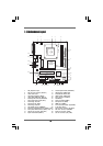
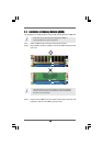
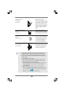
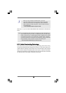
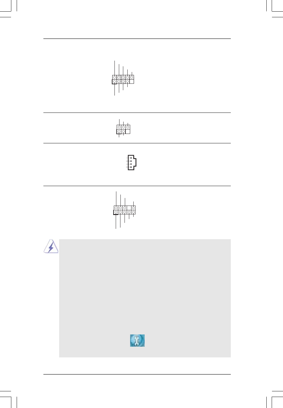
USB 2.0 Header HD 8CH I/O accommo-
(9-pin USB45) dates 4 default USB 2.0 ports. If
(see p.9 No. 19) those USB 2.0 ports on the I/O
panel are not sufficient, this
USB 2.0 header is available to
support 2 additional USB 2.0
ports.
Infrared Module Header This header supports an
(5-pin IR1) optional wireless transmitting
(see p.9 No. 18) and receiving infrared module.
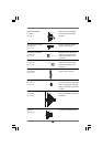
Internal Audio Connectors This connector allows you
(4-pin CD1) to receive stereo audio input
(CD1: see p.9 No. 27) from sound sources such as
a CD-ROM, DVD-ROM, TV
tuner card, or MPEG card.
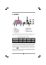
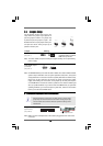
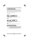
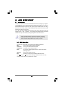
Front Panel Audio Header This is an interface for the front
(9-pin HD_AUDIO1) panel audio cable that allows
(see p.9, No. 25) convenient connection and
control of audio devices.
J_S ENSE
OUT2_L
1
MIC _RET
PRESENCE#
GND
OUT2_R
MIC 2_R
MIC 2_L
OUT_R ET
1. High Definition Audio supports Jack Sensing, but the panel wire on the
chassis must support HDA to function correctly. Please follow the
instruction in our manual and chassis manual to install your system.
2. If you use AC’97 audio panel, please install it to the front panel audio
header as below:
A. Connect Mic_IN (MIC) to MIC2_L.
B. Connect Audio_R (RIN) to OUT2_R and Audio_L (LIN) to OUT2_L.
C. MIC_RET and OUT_RET are for HD audio panel only. You don’t
need to connect them for AC’97 audio panel.
D. Enter BIOS Setup Utility. Enter Advanced Settings, and then select
Chipset Configuration. Set the Front Panel Control option from
[Auto] to [Enabled].
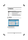
E. Enter Windows system. Click the icon on the lower right hand
taskbar to enter Realtek HD Audio Manager. Click “Audio I/O”, select
“Connector Settings” , choose “Disable front panel jack
detection”, and save the change by clicking “OK”.