


Page 6 Installation and Operation Manual
ELECTRICAL CONNECTIONS
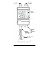
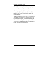
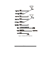
Units are supplied with 22 AWG free leads exiting from a ½”-14
NPT male conduit connection. The leads are-color coded and
marked. See Figure 2 for AC operation and Figure 3 for DC
operation.
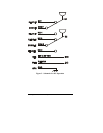
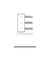
4-20 mA output (option letter V) is connected to the 2-pin
connector on the top-right of the unit per Figure 4, using the
supplied mating connector. This mating connector has solder cups
that will take wires as large as #18 AWG. See Chapter 4 for
operating instructions.
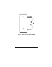
The RS232 communications (option letter Z) are connected to the
3-pin connector on the top-left of the unit (See Figure 5), using
the supplied mating connector. This mating connector has solder
cups that will take wires as large as #18 AWG. Cable length must
not exceed 50 feet. See Chapter 6 for operating instructions.
All field wiring for the 801P5 must comply with requirements of
the NEC or applicable local electrical codes.