


Page 5 801P5 Smart Switch
TM
WARNING
WARNING
WARNING
WARNING
CAUTION
CHAPTER
2
INSTALLATION
Installation of the Smart-Switch
TM
is relatively straightforward.
However, the Smart-Switch
TM
must be installed by a qualified
electrician, in compliance with all local and national electrical codes.
Electrical Hazard
Do not make electrical connections while power is on.
Always check for multiple circuits.
Always make sure grounding is adequate.
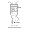
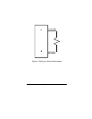
MOUNTING
The Smart-Switch
TM
can be mounted directly to the pressure
connection, or it can be attached to a flat surface, such as a wall,
near the connection to be monitored. For surface mounting, slide
the two mounting brackets into the slots on the back of the
Smart-Switc
TM
and use #10 (.190 in. dia.) fasteners.
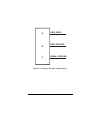
PRESSURE CONNECTION
The standard pressure connection for the 801P5 Smart-Switch
TM
is a ¼”- 18 NPT female pipe thread. A 7/16” - 20 SAE boss is
also available as Option E. When installing the Smart-Switch
TM
,
always:
• Make sure that the unit and your system have the same fittings.
• Use the wrench flats provided.
• Seal all joints with pipe joint sealing compound.
Avoid excessive torque on all threaded connections.