


Understanding Status LEDs
ERX Edge Routers
8-3
Understanding Status LEDs
When you power up the system, it runs a series of tests for each module
installed in the system. Refer to the tables in this section to understand
normal and abnormal LED activity. For troubleshooting information, see
Table 8-4.
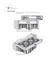
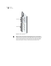
LED Identification
The system’s modules have two sets of status LEDs. The top set indicates
generic router and module status. The bottom set indicates
module-specific status, such as port status (line modules) or fan status
(SRP module).
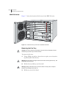
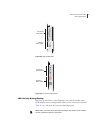
The number against the port status LED on a line module corresponds to
the number of the port on the I/O module. Some line modules have more
port status LEDs than the number of ports on the I/O module. In these
cases, only the LEDs for the corresponding ports on the I/O modules are
active.
For example, an OCx/STMx line module can pair with either an OC3-4
or an OC12/STM4 I/O module. Consequently, the line module has four
port status LEDs for OC3/STM1 operation. However, only the top two
sets of port status LEDs are active during OC12/STM4 operation.
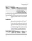
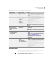
Table 8-2 shows the functions of the module and port status LEDs.
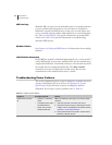
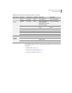
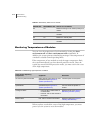
System shuts down. • Temperature too high
• Loss of power
Note: The following actions apply to all of the possible
problems.
1 Verify that power connections are properly attached.
2 Verify that system is receiving power.
3 Check whether or not the LEDs are lit.
4 Run diagnostics on SRP and line modules.
5 If system will not reset, contact Juniper Networks
Customer Service.
Table 8-1 Causes of power failures (continued)
Symptom Possible Problems Actions
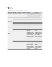
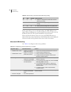
Table 8-2 LED identification and activity descriptions
LED Location LED Label LED Indicator LED Color OFF to ON ON to OFF
All modules
OK Module status Green Self-test passed Failure detected
FAIL Module status Red Failure detected Diagnostic test running
ONLINE Module status Green Module online Module offine