


Cabling the SRP I/O Module
ERX Edge Routers
4-9
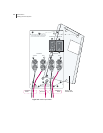
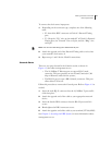
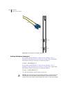
To connect the clock source input ports:
1 Depending on the connector type, complete one of the following
tasks:
• E1: Attach the BNC connector to Clock A’s External Timing
port.
• T1: Wrap the “Tip” wire on pin marked T of Clock A’s External
Timing port, the “Ground” wire on G pin, and the “Ring” wire
on R pin.
Note: You can use a wire-wrap gun to attach wires to pins.
2 Attach the opposite end of the External Timing cable or wires into
your network’s clock source A.
3 Repeat steps 1 and 2 for the Clock B connections.
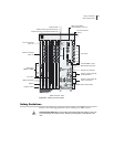
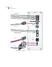
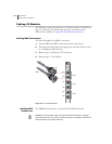
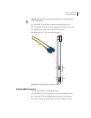
Console Ports
There are two ports located in the Console section (as shown in
Figure 4-3) that allow management access.
• The 10/100Base-T Ethernet port accepts an RJ-45 (male)
connector. This port provides an out-of-band connection. (We
ship an Ethernet cable with the system.)
• The RS-232 port accepts a DB-9 (female) connector. This port
allows direct CLI access.
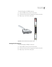
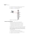
Follow this procedure to connect the Console ports. Refer to Figure 4-3 as
needed.
1 Insert the male RJ-45 connector into the 10/100Base-T port until it
clicks into place.
2 Attach the opposite end of the cable to your appropriate network
device.
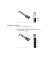
3 Insert the female DB-9 connector into the RS-232 port until it is
secure.
4 Hand-tighten the DB-9 connector screws.
5 Attach the opposite end of the cable to your terminal (VT100/ANSI).
See Chapter 5, Accessing the ERX System, for more information about
management access.