


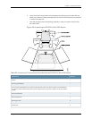
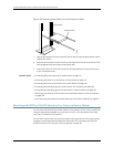
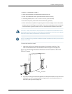
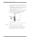

NOTE: If youneed tomount the switchin a recessed position on either a two-postrack
orafour-postrack,youcanusethe2-in.-recessfrontbracketsprovidedintheseparately
orderable four-post rack-mount kit.
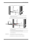
NOTE: If you are mounting an EX4200 switch on four posts, ensure that the rack is
27.5in. through 30.5in. deep if you will mount the switch flush with the rack front and
that the rack is 29.5 in. through 32.5 in. deep if youwill mount the switch 2 in. recessed
from the rack front, thus ensuring that the protective earthing terminal is accessible
through the opening in the rear bracket.
Before mounting the switch on four posts in a rack:
•
Verify that the site meets the requirements described in “Site Preparation Checklist
for EX3200 and EX4200 Switches” on page 87.
•
Place the rack in its permanent location, allowing adequate clearance for airflow and
maintenance, and secure it to the building structure.
•
Read “General Safety Guidelines and Warnings for EX Series Switches” on page 207,
with particular attention to “Chassis Lifting Guidelines for EX3200 and EX4200
Switches” on page 220.
•
Remove the switch from the shipping carton (see “Unpacking an EX3200 or EX4200
Switch” on page 118).
Ensure that you have the following parts and tools available:
•
Phillips (+) screwdriver, number 2
•
6 flat-head 4-40 mounting screws (provided with the four-post rack-mount kit)
•
12flat-head4x6-mmPhillipsmountingscrews(providedwiththefour-postrack-mount
kit)
•
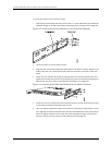
One pair each of flush or 2-in.-recess front brackets
•
One pair of side-rail brackets
•
One pair of rear brackets
•
Screws to secure the chassis and the rear brackets to the rack (not provided)
•
Dust covers for ports (for EX4200-24F switches only; optional)
CAUTION: If you are mounting multiple units on a rack, mount the heaviest unit at the
bottom of the rack and mount the other units from the bottom of the rack tothe topin
decreasing order of the weight of the units.
125Copyright©2010, JuniperNetworks, Inc.
Chapter9:Installing theSwitch