


To connect and configure the switch using the J-Web interface:
1. Transition the switch into initial setup mode:
•
EX2200 switch—Press the mode button located on the lower right corner of the
front panel for 10 seconds.
•
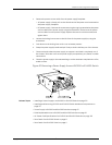
EX3200, EX4200, EX4500, or EX8200 switch—Use the Menu and Enter buttons
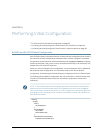
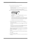
located to the right of the LCD panel (see Figure 66 on page 168):
Figure66: LCD Panelin an EX3200,EX4200,EX4500,or EX8200 Switch
1. Press the Menu button until you see MAINTENANCE MENU. Then press the
Enter button.
2. Press Menu until you see ENTER EZSetup. Then press Enter.
If EZSetup does not appear as an option in the menu, select Factory Default
toreturn the switch tothe factorydefault configuration. EZSetup is displayed
in the menu only when the switch is set to the factory default configuration.
3. Press Enter to confirm setup and continue with EZSetup.
2. Connect the Ethernet cable from the Ethernet port on the PC to the switch.
•
EX2200, EX3200, or EX4200 switch—Connect the cable to port 0 (ge-0/0/0) on
the front panel of the switch.
•
EX4500 switch—Connect the cable to the port labeled MGMT on the front panel
of the switch.
•
EX8200switch—ConnectthecabletotheportlabeledMGMTontheSwitchFabric
and Routing Engine (SRE) module in slot SRE0 in an EX8208 switch or on the
Routing Engine (RE) module in slot RE0 in an EX8216 switch.
TheseportsareconfiguredastheDHCPserverwiththedefaultIPaddress,192.168.1.1.
The switch can assign an IP address tothe managementPC in the IP address range
192.168.1.2 through 192.168.1.253.
3. From the PC, open a Web browser, type http://192.168.1.1 in the address field, and
press Enter.
4. On the J-Weblogin page, typeroot asthe username, leavethe passwordfield blank,
and click Login.
5. On the Introduction page, click Next.
6. On the Basic Settings page, modify the hostname, the root password, and date and
time settings:
Copyright ©2010,Juniper Networks,Inc.168
CompleteHardwareGuide forEX3200 andEX4200 EthernetSwitches