


• Optical Interface Support in EX3200 and EX4200 Switches on page 43
• Installing and Removing EX3200 and EX4200 Switch Hardware Components on
page 131
• Installing an Uplink Module in an EX3200 or EX4200 Switch on page 135
• Removing an Uplink Module from an EX3200 or EX4200 Switch on page 177
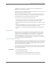
Rear Panel of an EX4200 Switch
The rear panel of the EX4200 switch consists of the following components:
•
Fan tray
•
Virtual Chassis ports (VCPs)
•
USB port
•
Temperature shutdown LED
•
Management Ethernet port
•
Console port
•
ESD point
•
Power supply or power supplies
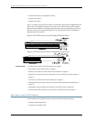
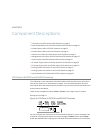
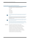
Figure 7 on page 11 shows the rear panel of an EX4200 switch. All EX4200 switches
have the same rear panel. The 320 W AC power supply and the 190 W DC are flush with
the chassis. The 600 W AC power supply and 930 W AC power supply extend out of the
chassis by 2.25 in. Power cord retainer clips extend out of the power supply by 3 in.
Figure 7: EX4200 Switch Rear Panel
g020084
Virtual
chassis
ports
USB
port
Management
Ethernet
port
Fan
tray
Console
port
Power
Supply 1
Power
Supply 0
Protective earthing
terminal (on side panel)
ESD
point
Temperature
shutdown LED
Related Topics • Field-Replaceable Units in EX3200 and EX4200 Switches on page 18
• Front Panel of an EX4200 Switch on page 9
• USB Port Specifications for an EX Series Switch on page 39
• Cooling System and Airflow in an EX4200 Switch on page 33
• Power Supply in EX3200 and EX4200 Switches on page 27
11Copyright©2010, JuniperNetworks, Inc.
Chapter1:EX3200 andEX4200 SwitchesOverview