


10
Controls and Features (cont.)
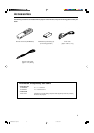
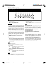
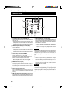
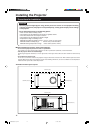
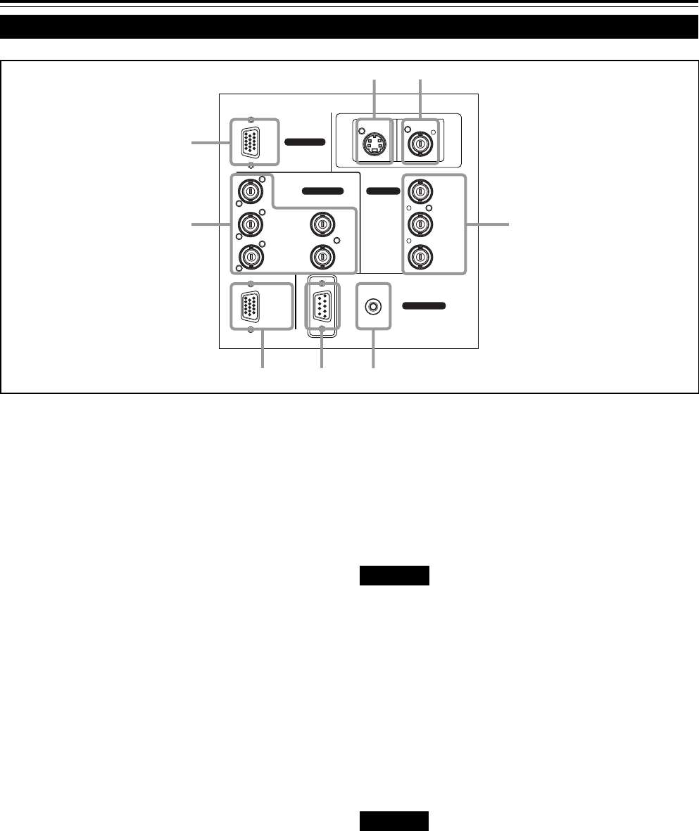
Connector Panel
1
Y/C (S video) input terminal (Mini DIN 4 pin)
Connect this terminal to the S video output terminal of a
video deck, etc.
* This terminal can be used if a video board (PK-G1101D)
sold separately has been installed. The terminal was not
provided when the projector was shipped from the factory.
2
VIDEO (composite video) input terminal (BNC)
Connect this terminal to the composite video output terminal
of a video deck, etc.
* This terminal can be used if a video board (PK-G1101D)
sold separately has been installed. The terminal was not
provided when the projector was shipped from the factory.
3
Y, PB/B-Y, PR/R-Y input terminals (BNC)
These are input terminals for component (Y, B-Y, R-Y)
signals or DTV-format (Y, P
B, PR) signals.
Device with component signal output terminals, such as
for NTSC and DTV-format, can be connected.
* For details about DTV-format signals (480i, 480p, 720p,
1080i) compatible with this unit, refer to page 66.
4
REMOTE terminal (mini jack)
This terminal is used to directly connect the remote con-
trol to the projector. Use the remote control cable supplied.
An infrared remote control extension unit can also be con-
nected to the jack.
5
RS-232C terminal (D-sub 9 pin)
This is a RS-232C interface-specified terminal. This
projector can be controlled by a computer connected
externally.
6
RGB OUT (RGB output) terminal (D-sub 3-row 15 pin)
The computer input signal projected on the screen is output.
A display unit can be used by connecting it to this terminal.
7
RGB IN (RGB input) -2 terminal (BNC)
These are input terminals for analog RGB signals, vertical
sync (V) signals, and horizontal sync (H) signals / composite
signals(Cs). Devices which have analog RGB signal output
terminals can be connected.
* Input of external sync signals is automatically
detected.
Detection of H/V signals or Cs signals causes automatic
switch to external sync. The priority order is H/V > Cs.
CAUTION
• When computer-related signals are input, the uppermost edge
of the screen may appear bowing if the sync signal input is
composite sync (Cs) or G on sync signal. In that case, use
separate sync signals for vertical sync (V) and horizontal sync
(H).
8
RGB IN (RGB input) -1 terminal (D-sub 3- row 15 pin)
This is an input terminal (PC) dedicated for computer
signals (RGB video signals and sync signals).
Connect the display output terminal of the computer to this
terminal. When a Macintosh or PC-9801/9802 series
computer is to be connected, use a suitable conversion
adapter separately available.
CAUTION
• When computer-related signals are input, the uppermost edge
of the screen may appear bowing if the sync signal input is
composite sync (Cs) or G on sync signal. In that case, use
separate sync signals for vertical sync (V) and horizontal sync
(H).
R
RGB
Y/C VIDEO
G H/CS
BV PR/R-Y
P
B/B-Y
Y
RGB OUT
RS-232C
REMOTE
RGB IN-2
CONTROL
EXT. IN
RGB IN-1
2
1
3
4
7
8
5
6
M5000LU/SCU p.05-13 01.3.5, 15:0410