


15
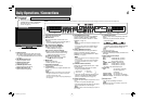
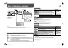
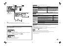
7 Using the serial communication
You can control the monitor from a personal computer etc. via RS-485 or RS-232C terminal.
• Consult your dealer if you want to know the detail of the external control specification.
<Communication specifications>
Input terminal Cable
Terminal
specification
Communication specifications
RS-485 A straight LAN cable
☞ the right
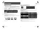
Baud Rate : 4800 bps
Data Bits : 8 bits
Parity : No parity
Stop Bits : 1 bit
Flow Control : No control
Communication Code : ASCII Code
RS-232C A straight cable with a D-sub 9-pin
connector (male for the monitor,
female for the personal computer
etc.)
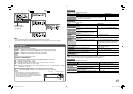
<Command outline>
• To start communication, send the connection command from the personal computer etc.
• To terminate the communication, send the termination command from the personal computer etc.
Example of communication procedures
• Commands starting with “!” are operation commands from the personal computer etc. For details, see <Command list> on the
right.
• Character strings starting with “@” are status returns from the monitor.
1 Starting the communication: connection command (!00BCN1Cr)
3 Selecting “SDI 1” input (!00BINACr)
5 Terminating the communication: termination command (!00BCN0Cr)
6 Monitor’s status (@00BOKCr)
4 Monitor’s status (@00BOKCr)
2 Monitor’s status (@00BOKCr)
Personal computer
etc.
Monitor
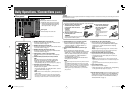
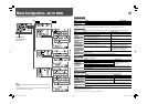
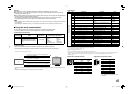
<Command list>
Type No. Commands Functions Data
Basic commands
1*
1
!
*
*
*
2
BCN1Cr Starts communication (connection) No data
2*
1
!
*
*
*
2
BCN0Cr Terminates communication (termination) No data
3!
*
*
*
2
BI DSETx
x*
3
Cr Assigns the control ID 01 – 99
4!
*
*
*
2
BI DRETCr Initializes the control ID No data
5!
*
*
*
2
BI DDSPx
x*
3
Cr Displays/hides the ID
00: Hide
01: Display
6!
*
*
*
2
BI DCHKx
x*
3
Cr
Flashes/hides the selected ID No. of the
monitor
00: Hide
01: Display
7!
*
*
*
2
BMENUCr
Displays the main menu/Quits the menu
operation
No data
8!
*
*
*
2
BUPCr
Moves the cursor upward ( )
No data
9!
*
*
*
2
BDOWNCr
Moves the cursor downward ( )
No data
10 !
*
*
*
2
BADJRCr
Makes setting/adjustment ( )
No data
11 !
*
*
*
2
BADJLCr
Makes setting/adjustment ( )
No data
12 !
*
*
*
2
BSETUPCr Displays the set-up menu No data
13*
1
!
*
*
*
2
BPW1 Cr Turns on the monitor No data
14 !
*
*
*
2
BPW0 Cr Turns off the monitor (standby) No data
15*
4
!
*
*
*
2
BI NACr Selects “SDI 1” input No data
16*
4
!
*
*
*
2
BI NBCr Selects “SDI 2” input No data
17 !
*
*
*
2
BI NCCr Selects “DVI” input No data
18 !
*
*
*
2
BI NDCr Selects “COMPO. / RGB” input No data
19 !
*
*
*
2
BI NECr Selects “VIDEO 1” input No data
20 !
*
*
*
2
BI NFCr Selects “VIDEO 2” input No data
21 !
*
*
*
2
BDI SPCr
Displays the status*
5
No data
22 !
*
*
*
2
BAMUTEx
x*
3
Cr Turns muting on/off 00: Off, 01: On
23 !
*
*
*
2
BASPx
x*
3
Cr Changes the aspect ratio 00: 4:3, 01: 16:9
• “Cr” is 0Dh.
*
1
These commands can be used while the monitor is off (standby).
*
2
“
**
” is monitor’s ID. Normally, set to “00.”
*
3
Enter the appropriate data to “xx”.
*
4
These commands are available for only DT-V24L1D and DT-V20L1D.
*
5
Displays the information shown when INPUT SELECT button of the current input is pressed (☞ “About the Status Display” on
page 7). While controlling with MAKE (make contact) system, the information is displayed only at the moment of
short-circuiting.
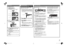
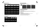
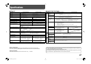
This is a female
terminal.
Pin No. IN terminal
signal
OUT terminal
signal
1
TXD + TXD +
2
TXD – TXD –
3
RXD + RXD +
4
NC NC
5
NC NC
6
RXD – RXD –
7
NC NC
8
GND GND
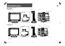
This is a female
terminal.
<Specifications of RS-232C terminal>
Pin No. Signal
1
NC
2
RXD
3
TXD
4
NC
5
GND
6
NC
7
RTS
8
CTS
9
NC
• The 7th terminal and the 8th terminal are
connected.
<Specifications of RS-485 terminal>
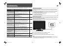
Operation
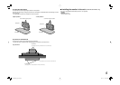
1 Set “PARALLEL TYPE” of “REMOTE SETTING” to “MAKE” or “TRIGGER” in the set-up menu.
2 Short-circuit the 7th pin terminal (external control) to the 8th pin terminal (GND) so that the monitor can be
controlled by the external control.
3 When selecting “MAKE” (make contact) system: Operate each function by short-circuiting the corresponding pin
terminal to the 8th pin terminal (GND) or opening it.
When selecting “TRIGGER” system: Operate each function by pulse control, that is short-circuiting the
corresponding pin terminal to the 8th pin terminal (GND) for about 1 second and opening it.
NOTE
• When changing the input with MAKE (make contact) system, only one pin terminal must be short-circuited. (Other pin terminals
must be opened.)
• When selecting the “TRIGGER” system, you can operate only one function at a time. Operate the functions one by one.
DT-V2420L1D_UA_R.indd 15DT-V2420L1D_UA_R.indd 15 06.11.17 10:40:23 AM06.11.17 10:40:23 AM