


8
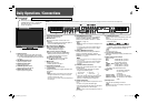
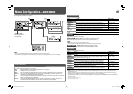
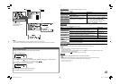
7 Rear panel
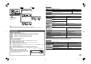
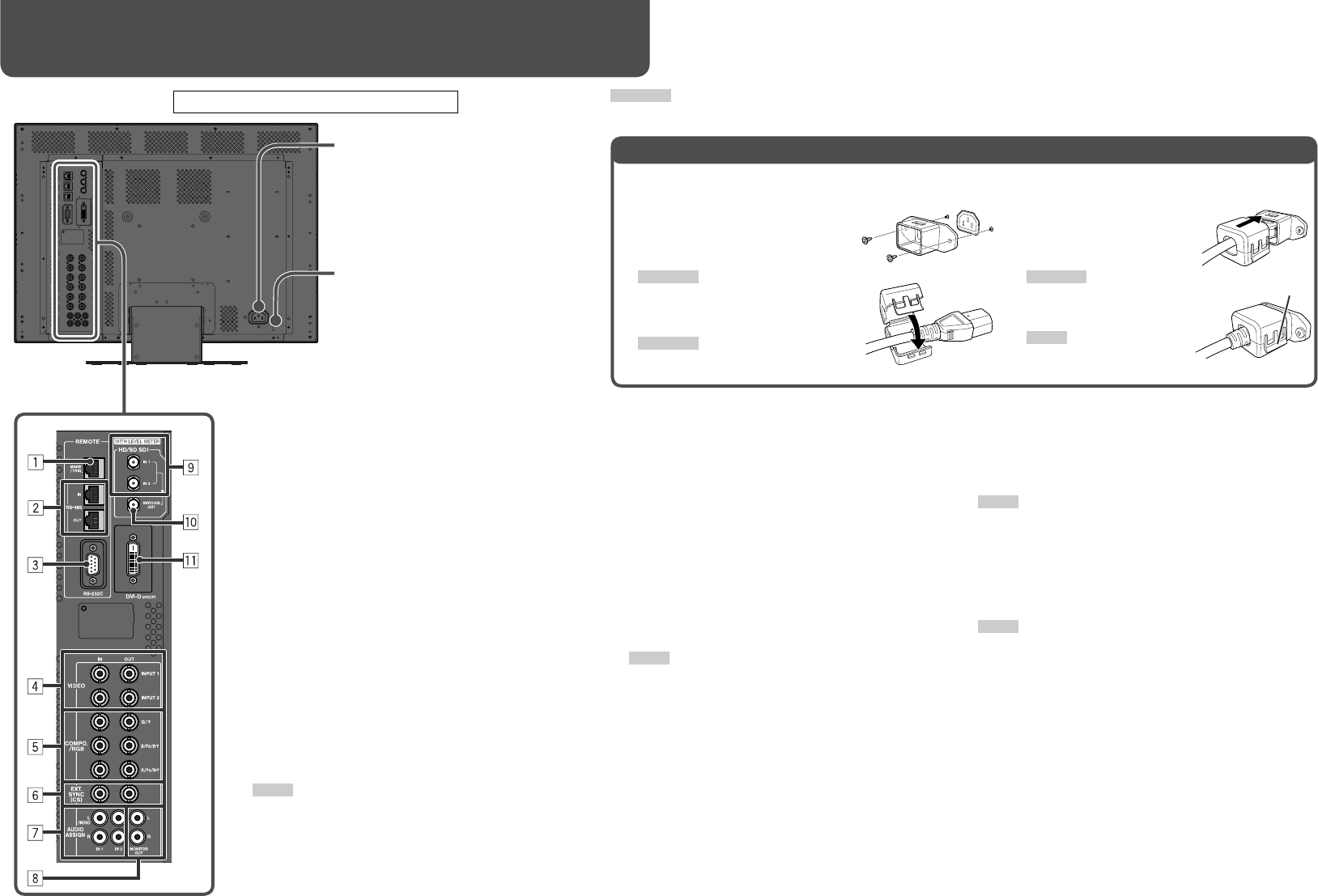
Daily Operations / Connections (cont.)
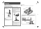
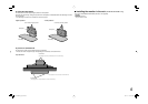
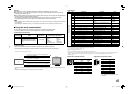
• The provided power cord holder prevents accidental disconnection of the AC power cord from the AC inlet.
• The power cord holder consists of two parts, a case and a cover.
1 Attach the power cord holder case
around the AC inlet on the rear
of the monitor with two screws
(provided).
CAUTION
Use only the provided screws.
2 Attach the power cord holder cover
to the AC power cord.
CAUTION
A different plug shape will result in the cover
being attached to a different position.
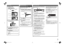
3 Plug in the AC power cord
to the AC inlet, and attach
the power cord holder
cover to the case.
CAUTION
Make sure the plug will not be
pulled out after the cover is
attached.
NOTE
To detach the cover, release
the tab.
Attaching the Power Cord Holder
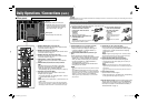
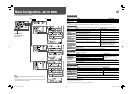
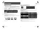
7 AUDIO ASSIGN (IN 1, IN 2) terminals (pin jack)
Input terminals for the analog audio signals.
• Select the video input to assign the audio signal
in “AUDIO1 ASSIGN.” or “AUDIO2 ASSIGN.” (☞
“AUDIO SETTING” on page 11).
8 AUDIO ASSIGN (MONITOR OUT) terminals (pin
jack)
Output terminals for the analog audio signal.
• The terminals output the audio signal through AUDIO
ASSIGN (IN 1) or AUDIO ASSIGN (IN 2) terminals
when you select the video input you have selected
for “AUDIO1 ASSIGN.” or “AUDIO2 ASSIGN.” in
“AUDIO SETTING” (☞ page 11).
• The EMBEDDED AUDIO signal is decoded into an
analog signal, then emitted.
NOTE
• The signal is output from this terminal only when the monitor
is on.
• The EMBEDDED AUDIO signal has priority over the audio
signal input to AUDIO ASSIGN (IN 1) or AUDIO ASSIGN (IN
2) terminals when “SDI 1” or “SDI 2” is selected for “AUDIO1
ASSIGN.” or “AUDIO2 ASSIGN.” and the EMBEDDED
AUDIO signal is input to HD/SD SDI (IN 1) or HD/SD SDI
(IN 2) terminal.
9 HD/SD SDI (IN 1, IN 2) terminals (BNC)
Input terminals for the HD SDI and SD SDI signals.
• The terminals accept also EMBEDDED AUDIO signals*
including up to 12 audio channels with the sampling
frequency of 48 kHz.
NOTE
The types of signals coming through the IN 1 and IN 2 terminals
are automatically recognized—HD SDI or SD SDI signal. Note,
however, that input is not changed automatically.
p HD/SD SDI (SWITCHED OUT) terminal (BNC)
Output terminal for the HD SDI and SD SDI signals.
• The SDI signal of the current input (SDI 1 or SDI 2) is
re-clocked and output.
NOTE
• When the input other than SDI 1 or SDI 2 is selected, the SDI
signal of the input selected last time is re-clocked and output from
this terminal.
• The signal is output from this terminal only when the monitor is
on.
q DVI-D (HDCP) terminal
Input terminal for the DVI-D signal.
• Select the signal type in “DVI INPUT SEL.” corresponding
to the type of the input signal (☞ page 10).
The illustration of the monitor is of DT-V24L1D.
Security slot
Install a security wire to this slot.
1 REMOTE (MAKE/TRIG.) terminal (RJ-45)
Ter minal for controlling the monitor by an external control.
☞ “External Control” on page 14
2 REMOTE (RS-485) terminals (RJ-45)
Ter minals for controlling the monitor by an external control.
☞ “External Control” on page 14
3 REMOTE (RS-232C) terminal (D-sub 9-pin)
Ter minal for controlling the monitor by an external control.
☞ “External Control” on page 14
4 VIDEO (INPUT 1, INPUT 2) terminals (BNC)
Input (IN) and output (OUT) terminals for the composite
signals.
5 COMPO./RGB (G/Y, B/PB/B-Y, R/PR/R-Y) terminals
(BNC)
Input (IN) and output (OUT) terminals for the analog
component (color difference) or analog RGB signals.
• Select the signal type in “COMPO./RGB SEL.”
corresponding to the type of the input signal (☞ page 10).
6 EXT.SYNC (CS) terminals (BNC)
Input (IN) and output (OUT) terminals for the external
composite sync (Cs) signals.
• To use these terminals, set “SYNC INPUT SEL.” to “EXT.”
☞ “SYNC FUNCTION” on page 11
NOTE
• The terminals are for all VIDEO (INPUT 1), VIDEO (INPUT 2) and
COMPO./RGB.
• When an external sync signal is input, external synchronization
has priority over all VIDEO 1, VIDEO 2 and COMPO./RGB input.
• The setting of “SYNC INPUT SEL.” is memorized for each input.
AC inlet
Power input connector. Connect the
provided AC power cord to an AC outlet.
• Attach the provided power cord holder
to prevent accidental disconnection of
the AC power cord (☞ the right).
Tab
*Using the audio level meter (DT-V24L1D and DT-V20L1D only)
You can check the conditions of the current EMBEDDED
AUDIO signals in the audio level meter. The setting for the
level meter is selected in “LEVEL METER SETTING” (☞
“AUDIO SETTING” on page 11).
DT-V24L1 and DT-V20L1 do not have 9 and p.
CAUTION
It is recommended not to use the power cord holder when installing the monitor in a monitor rack etc. where you cannot easily pull out the AC
power cord from an AC outlet.
DT-V2420L1D_UA_R.indd 8DT-V2420L1D_UA_R.indd 8 06.11.17 10:40:15 AM06.11.17 10:40:15 AM