


9
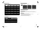
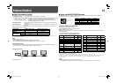
7 Available signals
The following signals are available for this monitor.
Video signals
No. Signal name
Input terminal
VIDEO
(INPUT1, INPUT2)
COMPO./RGB
(Analog component/
analog RGB)
HD/SD SDI (IN 1, IN 2)*
1
(DT-V24L1D and
DT-V20L1D only)
DVI-D (HDCP)
(Digital component/digital
RGB)
1 NTSC
√
———
2PAL
√
———
3 SECAM
√
———
4 BW(50Hz/60Hz)
√
———
5 480/60i —
√√
—
6 576/50i —
√√
—
7 480/60p —
√
—
√
8 576/50p —
√
—
√
9 640∗480/60p — — —
√
10 720/60p —
√√√
11 720/50p —
√√√
12 720/30p —
√√
—
13 720/25p —
√√
—
14 720/24p —
√√
—
15 1080/60i —
√√√
16 1035/60i — √*
2
√
—
17 1080/50i —
√√√
18 1080/60p — — —
√
19 1080/50p — — —
√
20 1080/30p —
√√√
21 1080/25p —
√√√
22 1080/24p —
√√√
23 1080/30psF — √*
3
√*
3
—
24 1080/24psF —
√√
—
√ :
Acceptable
— : Not acceptable
*
1
Compatible with EMBEDDED AUDIO
*
2
Displays the picture as 1080/60i, and “1080/60i” is displayed in the status display (☞ page 7).
*
3
“1080/60i” is displayed in the status display (☞ page 7).
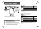
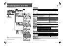
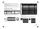
Computer signals (preset)
DVI-D (HDCP) terminals
No. Signal name
Screen resolution
Horizontal
frequency (kHz)
Vertical
frequency (Hz)
Scan system
Horizontal Vertical
1 VGA60 640 480 31.5 59.9 Non-interlace
2 WVGA60 852 480 31.5 59.9 Non-interlace
3 SVGA60 800 600 37.9 60.3 Non-interlace
4 XGA60 1024 768 48.4 60.0 Non-interlace
5 WXGA (1280) 1280 768 47.8 60.0 Non-interlace
6 SXGA60 1280 1024 64.0 60.0 Non-interlace
7 WSXGA+60 1680 1050 65.2 60.0 Non-interlace
8 UXGA60*
4
1600 1200 75.0 60.0 Non-interlace
9 WUXGA60*
4
1920 1200 74.0 59.9 Non-interlace
10 720/60p 1280 720 45.0 59.9/60.0 Non-interlace
11 1080/60p*
4
1920 1080 67.5 59.9/60.0 Non-interlace
*
4
For DT-V20L1D and DT-V20L1: When No. 8, 9 or 11 signal is input, thin lines will become obscured because their signal
resolution is higher than the screen resolution.
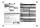
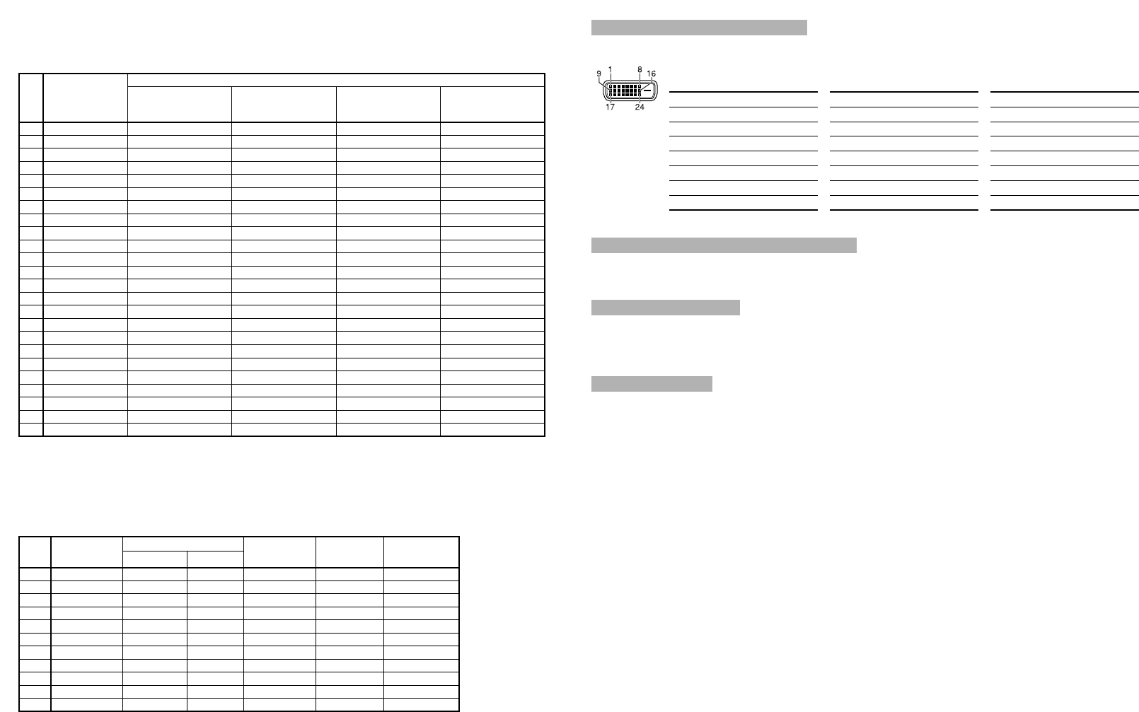
Specification of DVI-D (HDCP) terminal
Connect it to DVI-D output terminal on a personal computer.
Note for analog component/analog RGB signals
The monitor is compatible with G on sync, Y on sync and composite sync (Cs) signals. The monitor is not
compatible with separate sync (HS/VS) signals.
Note for computer signals
• Non-preset signals may not be displayed normally even if its frequency is within the acceptable range.
• When a preset signal is input, the signal format is displayed on the screen. For other signals, the resolution is
displayed.
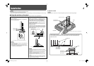
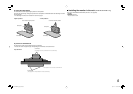
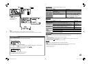
Note for connections
• Before making any connections, turn off all the equipment.
• Use a cord whose plugs correctly match the terminals on this monitor and the equipment.
• Plugs should be firmly inserted; poor connections could cause noise.
• When unplugging a cord, be sure to grasp its plug and pull it out.
• DO NOT connect the power cord until all connections are completed.
• Refer also to the user manual of each piece of equipment.
Pin
No.
Input signal
Pin
No.
Input signal
Pin
No.
Input signal
1
T.M.D.S Data 2–
9
T.M.D.S Data 1–
17
T.M.D.S Data 0–
2
T.M.D.S Data 2+
10
T.M.D.S Data 1+
18
T.M.D.S Data 0+
3
T.M.D.S Data 2 shield
11
T.M.D.S Data 1 shield
19
T.M.D.S Data 0 shield
4
NC
12
NC
20
NC
5
NC
13
NC
21
NC
6
DDC Clock
14
+5 V Power
22
T.M.D.S Clock shield
7
DDC Data
15
GND
23
T.M.D.S Clock+
8
NC
16
Hot Plug Detect
24
T.M.D.S Clock–
DT-V2420L1D_UA_R.indd 9DT-V2420L1D_UA_R.indd 9 06.11.17 10:40:17 AM06.11.17 10:40:17 AM