


13
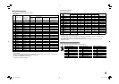
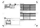
WAVE FORM SETTING*
1
Settings for the wave form monitor
Item To do Setting value
POSITION
Select the position of the wave form monitor. 1 (lower right), 2 (lower left), 3 (upper left),
4 (upper right)
FILTER
Activates/deactivates the low-pass filter for the
incoming wave form data.
FLAT (no filter), LOWPASS
GAIN
Adjust the gain level for the incoming wave form
data.
–10 – +10
OVER LEVEL
Select the over level for the incoming luminance
signals.
☞ “NOTE”
MARKING
Activates/deactivates the function to change the
color of a wave form when the signal exceeds the
limit specified on “LEVEL” (☞ below).
OFF, ON
LEVEL
Adjust the lower limit for the luminance signal 070 –109
AUTO OFF
Activates/deactivates the function to make the
wave form monitor indication go off automatically
15 minutes after displaying it.
ON, OFF
*
1
This function does not work for the signals as follows:
RGB input signals (analog/digital), DVI signals (digital/inputted from personal computer), 1080/60p (analog/digital),
1080/50p (analog/digital), 640 *480/60p (analog/digital).
SYNC FUNCTION
Settings for the synchronization with signals
Item To do Setting value
NO SYNC ACTION
Select the screen status when no signal is
coming in.
OFF,
P. SAVE (power save mode),
GRAY B. (gray screen)
DELAY TIME
Select the period until the screen status
changes as selected in “NO SYNC ACTION”
after signals stop coming in.
30sec., 5min., 15min.
SYNC INPUT SEL.*
2
Select the sync signal for the VIDEO1, VIDEO2
and COMPO./RGB input.
INT. (Internal sync), EXT. (External sync)
LOW LATENCY
Activates/deactivates the function to shorten
the time taken to display the picture (low latency
function).
• If the picture is not displayed steadily while
“ON” is selected, select “OFF.”
• While “ON” is selected, the displayed picture
may become unstable when an operation
using buttons on the front panel or the menu
is performed, or when the signal format
changes.
ON, OFF
• When setting “NO SYNC ACTION” to “GRAY B.,” the screen color changes to gray and the power consumption
of the back light is saved by half.
Selecting “P.SAVE” (power save mode) saves more power consumption by turning off the back light.
*
2
Memorized for each input.
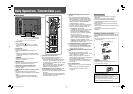
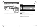
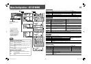
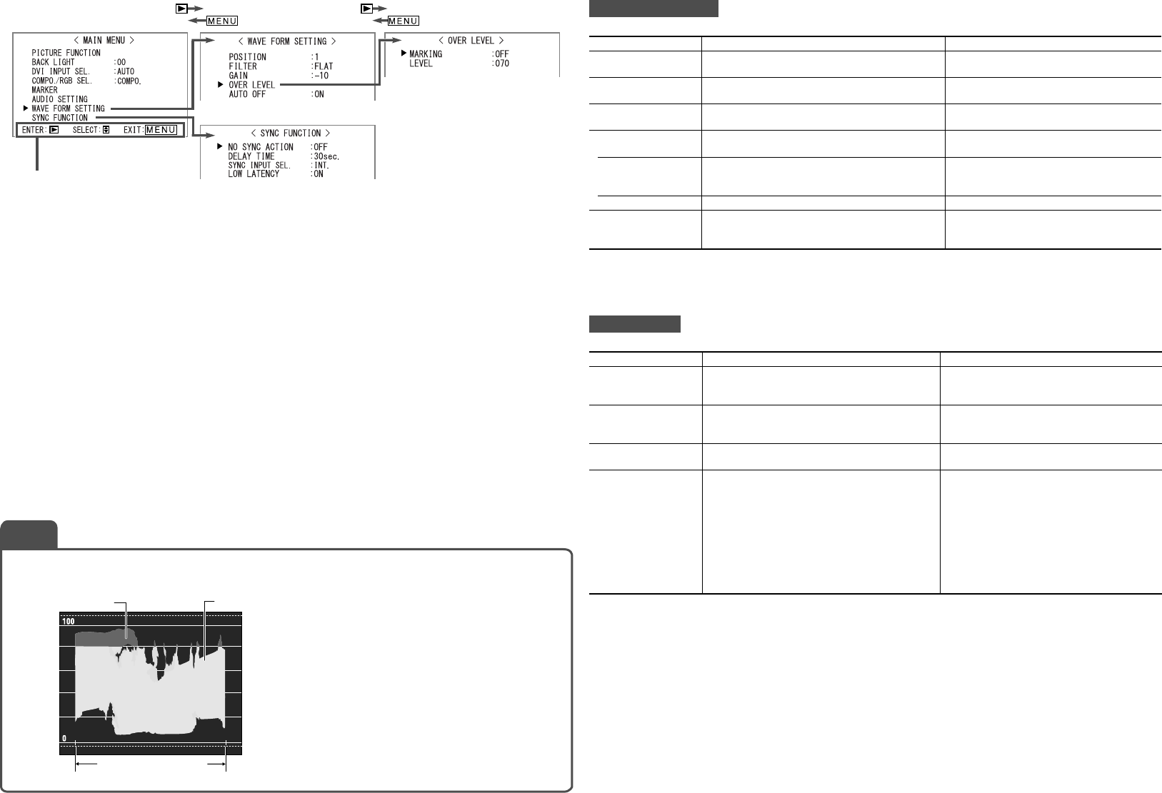
Operation guide
Shows the buttons for each
operation.
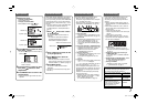
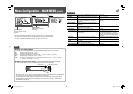
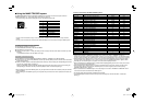
Example of the wave form monitor
Ex.: When “MARKING” is set to “ON” and “LEVEL” is set to “080”
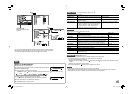
NOTE
• The wave which goes over the value set on “LEVEL”
is indicated in Red.
Red
White
Start End
Video signal
DT-V24_20L3D_EN.indd 13DT-V24_20L3D_EN.indd 13 08.5.27 5:15:06 PM08.5.27 5:15:06 PM