


9
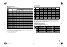
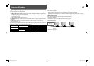
7 Available signals
The following signals are available for this monitor.
Video signals
No. Signal name
Signal format
shown in the
status display
(☞ page 7)
Input terminal
VIDEO
(INPUT1,
INPUT2)
COMPO./RGB
(Analog
component/
Analog RGB)*
1
E. AUDIO HD/
SD SDI
(IN 1, IN 2)*
2
DVI-D (HDCP)
(Digital component/
digital RGB)
1 NTSC NTSC
√
—— —
2PAL PA L
√
—— —
3 B/W50 B/W50
√
—— —
4 B/W60 B/W60
√
—— —
5 480/60i 480/60i —
√√ √
6 576/50i 576/50i —
√√ √
7 480/60p 480/60p —
√
—
√
8 576/50p 576/50p —
√
—
√
9 640*480/60p 640*480/60p — — —
√
10 720/60p 720/60p —
√√ √
11 720/50p 720/50p —
√√ √
12 720/30p 720/30p —
√√
—
13 720/25p 720/25p —
√√
—
14 720/24p 720/24p —
√√
—
15 1080/60i 1080/60i —
√√ √
16 1035/60i 1035/60i — √*
3
√
√*
3
17 1080/50i 1080/50i —
√√ √
18 1080/60p 1080/60p — — —
√
19 1080/50p 1080/50p — — —
√
20 1080/30p 1080/30p —
√√ √
21 1080/25p 1080/25p —
√√ √
22 1080/24p 1080/24p —
√√ √
23 1080/30psF 1080/60i — √*
3
√*
3
—
24 1080/24psF 1080/24psf —
√√
—
√: Acceptable
—: Not acceptable
*
1
Analog component/analog RGB signals are compatible with G on sync signal, Y on sync signals, and composite sync
signals (CS). The separate sync signal (HS/VS) is not compatible.
*
2
Compatible with EMBEDDED AUDIO signals
*
3
The signal is recognized as 1080/60i.
Computer signals (preset)
DVI-D (HDCP) terminals
No. Signal name
Resolution Frequency
Scan system
Horizontal Vertical Horizontal (kHz) Vertical (Hz)
1VGA60 640 480 31.5 59.9 Non-interlace
2WVGA60 852 480 31.5 59.9 Non-interlace
3SVGA60 800 600 37.9 60.3 Non-interlace
4XGA60 1024 768 48.4 60.0 Non-interlace
5WXGA (1280) 1280 768 47.8 60.0 Non-interlace
6WXGA+60
1440 900 55.9
60.0 Non-interlace
7SXGA60 1280 1024 64.0 60.0 Non-interlace
8WSXGA+60 1680 1050 65.2 60.0 Non-interlace
9UXGA60*
4
1600 1200 75.0 60.0 Non-interlace
10 WUXGA60*
4
1920 1200 74.0 60.0 Non-interlace
11 720/60p 1280 720 45.0 60.0 Non-interlace
12 1080/60p*
4
1920 1080 67.5 60.0 Non-interlace
13
720/50p 1280 720
37.5
50.0 Non-interlace
14
1080/50p*
4
1920 1080
56.25
50.0 Non-interlace
*
4
For DT-V20L3D: When No. 9, 10, 12 or 14 signals come in, thin lines will become obscured because their signal
resolution is higher than the screen resolution.
• Non-preset signals may not be displayed normally even if their frequency is within the acceptable range (☞
“Horizontal/vertical frequency (computer signal)” on page 21).
• When a preset signal comes in, the signal format is shown on the status display. For other signals, the
resolution is shown.
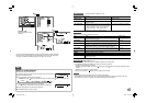
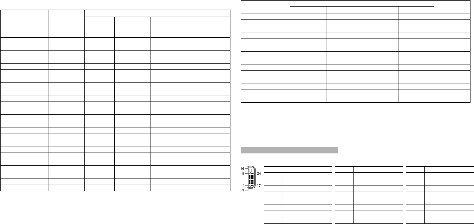
Specification of the DVI-D (HDCP) terminal
Connect it to the DVI-D output terminal on a personal computer.
Pin No. Input signal Pin No. Input signal Pin No. Input signal
1
T.M.D.S Data 2–
9
T.M.D.S Data 1–
17
T.M.D.S Data 0–
2
T.M.D.S Data 2+
10
T.M.D.S Data 1+
18
T.M.D.S Data 0+
3
T.M.D.S Data 2 shield
11
T.M.D.S Data 1 shield
19
T.M.D.S Data 0 shield
4
NC
12
NC
20
NC
5
NC
13
NC
21
NC
6
DDC Clock
14
+5 V Power
22
T.M.D.S Clock shield
7
DDC Data
15
GND
23
T.M.D.S Clock+
8
NC
16
Hot Plug Detect
24
T.M.D.S Clock–
DT-V24_20L3D_EN.indd 9DT-V24_20L3D_EN.indd 9 08.5.27 6:00:48 PM08.5.27 6:00:48 PM