


1-4 (No.XE007)
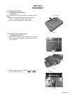
3.1.3 Removing the top case and LCD panel assembly
(See Figure 5 to Figure 10)
• Prior to performing the following procedure, remove the key-
board assembly.
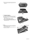
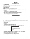
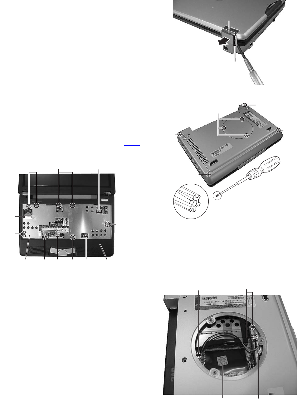
(1) Insert a single-slotted screwdriver or a flat screwdriver in a
space b on the underside of the hinge cover. Then, remove
the hinge cover by pulling the screwdriver in the direction
indicated by the arrow.And then, remove one more hinge
cover at the other side of the main body.
Fig.5
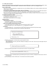
(2) Remove the eight screws B attaching the top case.
Screw B : 13-MAKXC60W(M2 x 6L(K)W-NI)
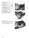
(3) Reverse the main body, and remove the four screws C on
the bottom of the main body.
Screw C : 13-MBSOC120W(M2 x 12L(S)W-NI, NY)
A special screwdriver is used when removing screw C.
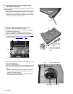
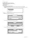
(4) Disconnect the connector wire from the connector CON2
on the main board. Similarly, remove the connector wires
from the connectors CON5
, CON6, and CN3.
Fig.6
Fig.7
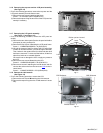
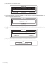
(5) Remove the three screws N attaching the DIMM cover, and
remove the DIMM cover.
Screw N : 13-MBKXC031W
The connection part of two wires connected to the LAN
board in a main board reverse side is pinched and re-
moved.
• When re-connecting, the wire of a gray is connected to
the ”AUX” terminal on a LAN board, and a black wire con-
nected to the “MAIN” terminal.
Moveover, please connect with a LAN board through a
wire in the hole on a main board.
Fig.8
Space b
Hinge cover
Hinge cover
B
BB
B
BB
CON2
CN3
CON5 CON6
Shield plate
Top case
C
N
C
C
C
A special screwdriver
is used when removing
screw C.
Part name : SCREW DRIVER
Part number : 22-240000310
DIMM cover
DIMM cover
Wire connection part
Hole
Main board LAN board