


1-6 (No.XE007)
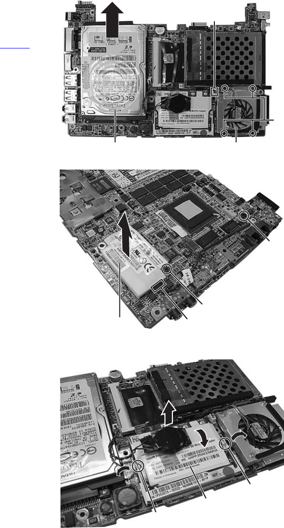
3.1.5 Removing the parts on the main board
(See Figure 13 to 15)
• Prior to performing the following procedure, remove the main
board.
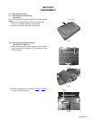
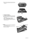
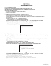
*Removing the fan assembly
(1) Remove the four screws F attaching the fan assembly.
(2) Disconnect the connector wire from the connector CON14
on the main board.
Screw F : 13-MBKXC031W(M2 x 3L(K,D3.4)W-NI,NY)
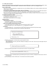
*Removing the hard disc drive
(1) Remove one screw G at the side of the main board where
the hard disc drive is not attached.
(2) Remove the hard disc drive by moving the hard disc drive
in the direction indicated by the arrow.
(3) HDD BRACKET (two places) installed in the side of the
hard disk drive is removed.
Screw G : 13-MAKXF030B(M3 x 3L(K)B-NI)
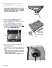
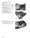
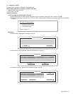
*Removing the modem pack
(1) Remove one screw H attaching the modem pack.
Screw H : 13-041203210(M2 x 3L(K)B-NI)
(2) Pull out the socket wire connected to the modem pack.
(3) Lift the modem pack, and remove it.
Fig.13
Fig.14
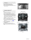
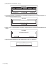
*Removing the LAN board assembly
(1) Since a LAN board will be lifted upwards if the e section of
LAN board both ends is extended outside, it draws out as
it is.
(2) When attaching, it is a procedure contrary to the time of re-
moving, a LAN board is aslant inserted to a socket, and a
LAN board is pushed until it is fixed.
Fig.15
Hard disc drive Fan assembly
CON14
F
Modem pack
H
G
Socket
e
e
LAN Board