


(No.XE007)1-7
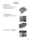
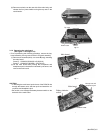
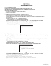
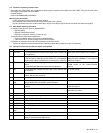
3.1.6 Removing the top case and the LCD panel assembly
(See Figure 16)
• Prior to the following procedure, remove the top case and the
LCD panel assembly from the bottom case.
(1) Remove the two screws I attaching the hinge.
Screw I : 13-041206211(M2 x 6L(K)B-NI NY)
(2) Remove the tapes fixing the two wires of the LCD panel as-
sembly if necessary.
Fig.16
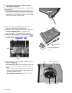
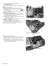
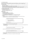
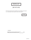
3.1.7 Removing the LCD panel assembly
(See Figure 17 and Figure 18)
• Prior to the following procedure, remove the LCD panel as-
sembly.
(1) Remove the two rubber pads (fixed to the panel with adhe-
sive tapes) by using a sharp tool.
(2) Remove the two screws J attaching the LCD panel frame.
Screw J : 13-MBKXD040W(M2.5 x 4L(K)W-NI,NY)
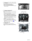
(3) Lift and the centers of the four sides of the LCD panel from
inside to an outward direction. (It is soft enough to be lifted.)
Then, latches in the centers of the four sides and also other
latches are removed. To remove all the latches, lift the four
sides from inside to an outward direction.
*Be careful not to damage the LCD or apply any stress to
the LCD.
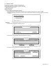
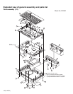
(4) Remove the two screws K attaching the LCD.
Screw K : 13-MBKXD040W(M2.5 x 4L(K)W-NI,NY)
(5) Remove one screw L attaching the inverter board, and dis-
connect the socket wire from the connector CN2
on the in-
verter board.
Screw L : 13-MAK2C023B(M2 x 2.3L(K,Ø4.9)B-NI)
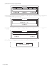
3.1.8 Remove the LAN antenna
(See Figure 18)
• Prior to the following procedure, remove the LCD.
(1) Remove the two screws M attaching the LAN antenna.
(2) Remove the tapes fixing the wire of LAN antenna if neces-
sary.
Fig.17
Fig.18
I
I
Rubber pad and screw J
LCD
LCD
Latch
Latch Latch
Latch
Inverter board
K
LCD
LCD
K
Q
L
LAN Antenna
M
LAN Antenna
M