


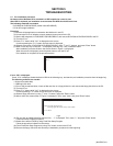

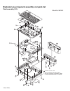
(No.XE007)1-5
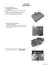
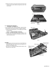
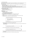
(6) Remove one latch c on the rear side of the main body, and
release the four joints d while moving the top case in the
rear direction.
Fig.9
Fig.10
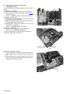
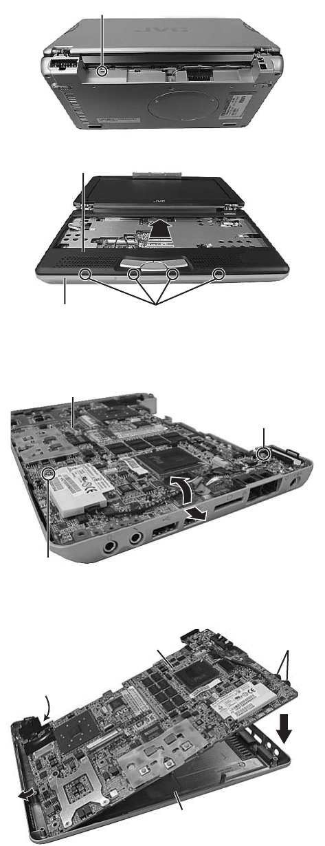
3.1.4 Removing the main board
(See Figure 11 and Figure 12)
• Prior to performing the following procedure, remove the key-
board assembly, the top case, and the LCD panel assembly.
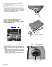
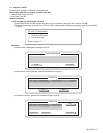
(1) Remove one screw D (short), one screw E (long), attaching
the main board.
Screw D : 13-MAKXC060W(M2 x 6L(K)W-NI)
Screw E : 13-MAKXC100W(M2 x 10L(K)W-NI)
(2) Lift the main board while pushing the microphone and
headphone jack in the direction indicated by the arrow, and
remove the main board.
Fig.11
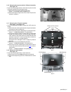
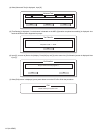
CAUTION:
• In attaching the main board, put the lever of the PCMCIA slot
through the bottom case, and then push and attach the mi-
crophone and headphone jack.
• Be careful not to damage the battery detector switch on the
backside of the main board.
Fig.12
Latch c
Joint d
Bottom case
Top case
1
1
2
2
Main board
D
E
Microphone and
headphone jack
2
2
1
Main board
Bottom case
Battery detector
switch