


1313
1313
13
2.7 Jumpers Setup2.7 Jumpers Setup
2.7 Jumpers Setup2.7 Jumpers Setup
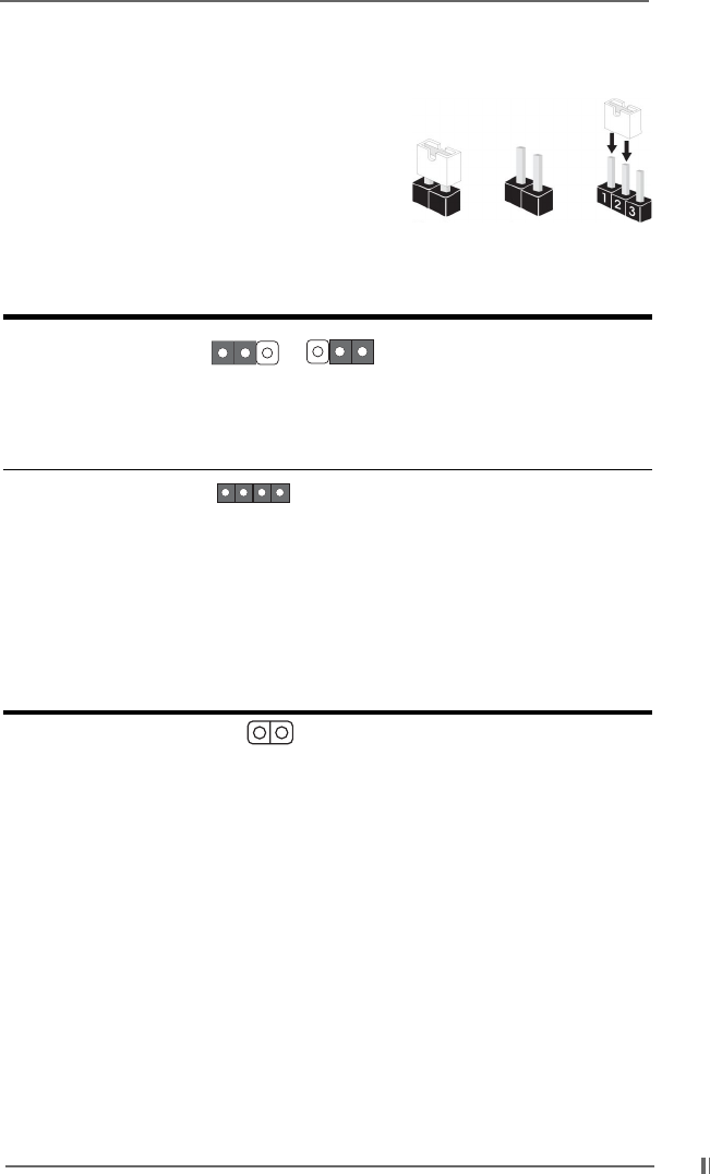
2.7 Jumpers Setup
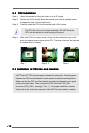
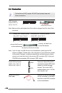
The illustration shows how jumpers are
setup. When the jumper cap is placed on
pins, the jumper is “Short”. If no jumper cap
is placed on pins, the jumper is “Open”. The
illustration shows a 3-pin jumper whose pin1
and pin2 are “Short” when jumper cap is
placed on these 2 pins.
Jumper Setting
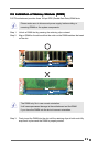
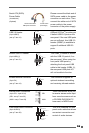
PS2_USB_PWR1 Short pin2, pin3 to enable
(see p.7 item 20) +5VSB (standby) for PS/2
or USB wake up events.
Note: To select +5VSB, it requires 2 Amp and higher standby current provided
by power supply.
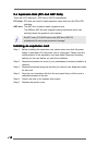
JR1(see p.7 item 27)
JL1(see p.7 item 26)
Note: If the jumpers JL1 and JR1 are short, both the front panel and the rear panel
audio connectors can work.
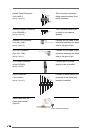
Clear CMOS
CLRCMOS1
(see p.7 item 14)
Note: CLRCMOS1 allows you to clear the data in CMOS. The data in CMOS includes
system setup information such as system password, date, time, and system
setup parameters. To clear and reset the system parameters to default setup,
please turn off the computer and unplug the power cord, then use a jumper
cap to short the pins on CLRCMOS1 for 3 seconds. Please remember to
remove the jumper cap after clearing the CMOS.
2-pin jumper
+5V
1_2
+5VSB
2_3
Short
Open
JR1 JL1