


1515
1515
15
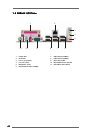
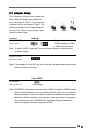
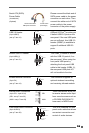
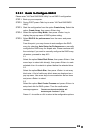
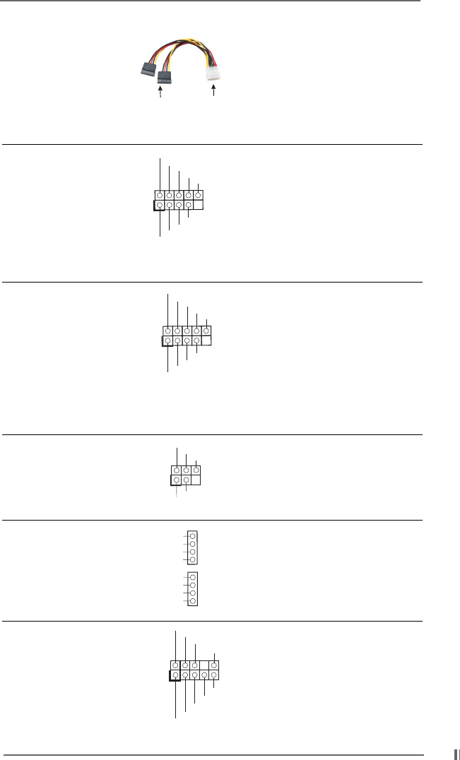
Serial ATA (SATA) Please connect the black end of
Power Cable SATA power cable to the power
(4-conductor) connector on each drive. Then
(Optional) connect the white end of SATA
power cable to the power
connector of the power supply.
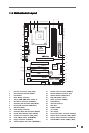
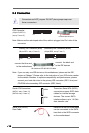
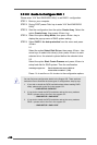
USB 2.0 Header ASRock I/O Plus
TM
provides you
(9-pin USB67) 6 default USB 2.0 ports on the
(see p.7 item 19) rear panel. If the rear USB ports
are not sufficient, this USB 2.0
header (USB67) is available to
support 2 additional USB 2.0
ports.
Shared USB 2.0 Header This USB4_5 header is shared
(9-pin USB4_5) with the USB 2.0 ports 4,5 on
(see p.7 item 31) the rear panel. When using the
front panel USB ports by
attaching the front panel USB
cable to this header (USB4_5),
the rear panel USB ports 4,5
will not be able to function.
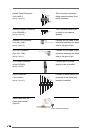
Infrared Module Connector This connector supports an
(5-pin IR1) optional wireless transmitting
(see p.7 item 18) and receiving infrared module.
Internal Audio Connectors These connectors allow you
(4-pin CD1, 4-pin AUX1) to receive stereo audio input
(CD1: see p.7 item 30) from sound sources such as
(AUX1: see p.7 item 29) a CD-ROM, DVD-ROM, TV
tuner card, or MPEG card.
Front Panel Audio Connector This is an interface for front
(9-pin AUDIO1) panel audio cable that allows
(see p.7 item 28) convenient connection and
control of audio devices.
connect to the
power supply
connect to the SATA
HDD power connector
DUMMY
GND
+5V
IRTX
IRRX
1
USB_PWR
USB_PWR
P+5
P-5
P+4
P-4
GND
GND
DUMMY
1
CD-R
GND
GND
CD-L
AUX-R
GND
GND
AUX-L
CD1
AUX1
USB_PWR
USB_PWR
P+7
P-7
P+6
P-6
GND
GND
DUMMY
1
GND
GND
+5VA
BACKOUT-R
BACKOUT-L
AUD-OUT-L
AUD-OUT-R
MIC-POWER
MIC
1