


KRAMER: SIMPLE CREATIVE TECHNOLOGY
Your TP-125 / TP-126
8
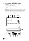
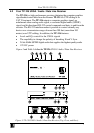
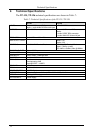
Table 3: TP-126 UXGA / Audio / Data Line Receiver (Top, Front, and Rear) Features
# Feature Function
1 12V DC +12V DC connector for powering the unit
2 S/PDIF RCA connector Connects to the digital audio acceptor
3
AUDIO
OUT
ANALOG 3.5mm Mini Jack Connects to the analog audio acceptor
4 RS-232 Terminal Block Connector Connects to the controlled unit
5 LINE IN RJ-45 Connector
Connects to
1
the LINE OUT RJ-45 connector on the TP-125
6 UXGA OUT 15-pin HD (F) Connector Connects to the UXGA acceptor
7 ON LED Illuminates when receiving power
8 EQ.
2
Trimmer Adjusts the cable compensation equalization level
9 LEVEL Trimmer Adjusts the output signal level
10 LINK LED Illuminates when receiving the correct input signal
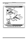
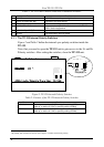
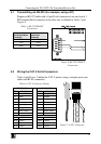
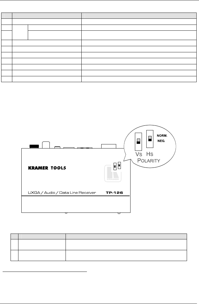
4.2.1 Your TP-126 UXGA / Audio / Data Line Receiver (Underside)
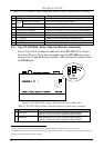
Figure 4 and Table 4 define the underside of the TP-126 UXGA / Audio /
Data Line Receiver. Note, that you need to open the TP-126 unit to gain
access to the Vs and Hs Polarity switches. After setting the switches, close
the TP-126 unit.
Figure 4: TP-126 UXGA / Audio / Data Line Receiver (Underside)
Table 4: TP-126 UXGA / Audio / Data Line Receiver (Underside) Features
# Feature Function
1 VS Switch Slide down to set the V SYNC to negative polarity (NEG);
slide up
1
to set the V SYNC to positive polarity (NORM)
2 HS Switch Slide down to set the H SYNC to negative polarity (NEG);
slide up
1
to set the H SYNC to positive polarity (NORM)
1 Using a UTP cable with CAT 5 connectors at both ends (the PINOUT is defined in Figure 7 and Table 6)
2 Degradation and UXGA signal loss can result from using long cables (due to stray capacitance), sometimes leading to a
total loss of sharpness in high-resolution signals