


KRAMER: SIMPLE CREATIVE TECHNOLOGY
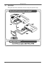
Your TP-125 / TP-126
6
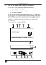
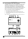
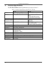
Table 1: TP-125 UXGA / Audio / Data Line Transmitter Features
# Feature Function
1 12V DC +12V DC connector for powering the unit
2 AUDIO IN 3.5mm Mini Jack Connects to the audio source
3 RS-232 Terminal Block Connector Connects to the PC or the Remote Controller (see section 5.1)
4 LINE OUT RJ-45 Connector
Connects to the LINE IN RJ-45 connector on the TP-126
UXGA / Audio Line Receiver
5 UXGA IN 15-pin HD (F) Connector Connect to the UXGA source
6 ON LED Illuminates when receiving power
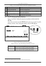
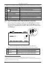
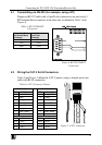
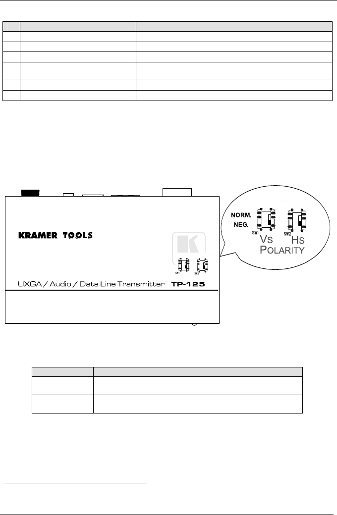
4.1.1 The TP-125 Internal Polarity Switches
Figure 2 and Table 2 define the internal sync polarity switches inside the
TP-125.
Note, that you need to open the TP-125 unit to gain access to the Vs and Hs
Polarity switches. After setting the switches, close the TP-125 unit.
Figure 2: TP-125 Internal Polarity Switches
Table 2: Features of the TP-125 Internal Polarity Switches
Feature Function
VS Switch Slide down to set the V SYNC to negative polarity (NEG);
slide up
1
to set the V SYNC to positive polarity (NORM)
HS Switch Slide down to set the H SYNC to negative polarity (NEG);
slide up
1
to set the H SYNC to positive polarity (NORM)
1 By default, both switches are set down (for a negative V SYNC and H SYNC polarity)