


Contents
i
Contents
1
Introduction 1
2
Getting Started 1
2.1
Quick Start 2
3
Overview 3
3.1
Shielded Twisted Pair (STP) / Unshielded Twisted Pair (UTP) 3
3.2
Recommendations for Achieving the Best Performance 4
4
Your TP-125 / TP-126 4
4.1
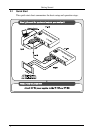
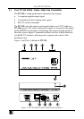
Your TP-125 UXGA / Audio / Data Line Transmitter 5
4.1.1
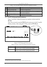
The TP-125 Internal Polarity Switches 6
4.2
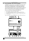
Your TP-126 UXGA / Audio / Data Line Receiver 7
4.2.1
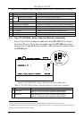
Your TP-126 UXGA / Audio / Data Line Receiver (Underside) 8
5
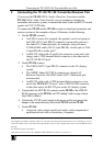
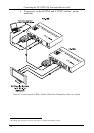
Connecting the TP-125/TP-126 Transmitter/Receiver Pair 9
5.1
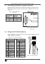
Transmitting via RS-232 (for example, using a PC) 11
5.2
Wiring the CAT 5 RJ-45 Connectors 11
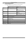
6
Technical Specifications 12
Figures
Figure 1: TP-125 UXGA / Audio / Data Line Transmitter 5
Figure 2: TP-125 Internal Polarity Switches 6
Figure 3: TP-126 UXGA / Audio / Data Line Receiver (Top, Front, and Rear) 7
Figure 4: TP-126 UXGA / Audio / Data Line Receiver (Underside) 8
Figure 5: Connecting the UXGA / Audio / Data Line Transmitter / Receiver System 10
Figure 6: RS-232 PINOUT Connection 11
Figure 7: CAT 5 Connector 11
Tables
Table 1: TP-125 UXGA / Audio / Data Line Transmitter Features 6
Table 2: Features of the TP-125 Internal Polarity Switches 6
Table 3: TP-126 UXGA / Audio / Data Line Receiver (Top, Front, and Rear) Features 8
Table 4: TP-126 UXGA / Audio / Data Line Receiver (Underside) Features 8
Table 5: RS-232 PINOUT Connection 11
Table 6: CAT 5 Connector Pinout 11
Table 7: Technical Specifications of the TP-125 / TP-126 12