


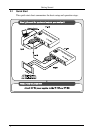
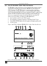
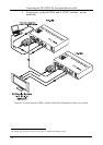
Connecting the TP-125/TP-126 Transmitter/Receiver Pair
11
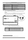
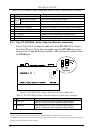
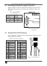
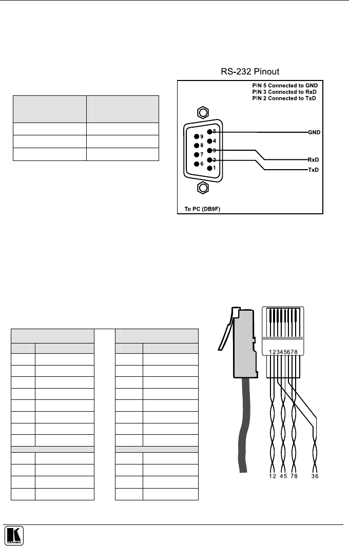
5.1 Transmitting via RS-232 (for example, using a PC)
Prepare an RS-232 cable with a 9-pin D-sub connector at one end, and a 3
PIN terminal block connector at the other end, as defined in Table 5 and
Figure 6:
Table 5: RS-232 PINOUT
Connection
Connect this PIN on
the Terminal Block
Connector:
To this PIN on the
9-pin D-sub
Connector
TxD PIN 2
RxD PIN 3
GND PIN 5
Figure 6: RS-232 PINOUT
Connection
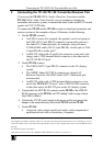
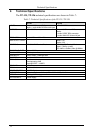
5.2 Wiring the CAT 5 RJ-45 Connectors
Table 6 and Figure 7 define the CAT 5 pinout, using a straight pin-to-pin
cable with RJ-45 connectors:
Table 6: CAT 5 Connector Pinout
EIA /TIA 568A EIA /TIA 568B
PIN Wire Color PIN Wire Color
1 Green / White 1 Orange / White
2 Green 2 Orange
3 Orange / White 3 Green / White
4 Blue 4 Blue
5 Blue / White 5 Blue / White
6 Orange 6 Green
7 Brown / White 7 Brown / White
8 Brown 8 Brown
Pair 1 4 and 5 Pair 1 4 and 5
Pair 2
3 and 6 Pair 2 1 and 2
Pair 3 1 and 2 Pair 3 3 and 6
Pair 4 7 and 8
Pair 4 7 and 8
Figure 7: CAT 5 Connector