


KRAMER: SIMPLE CREATIVE TECHNOLOGY
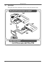
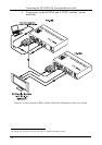
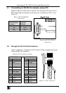
Connecting the TP-125/TP-126 Transmitter/Receiver Pair
10
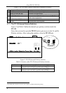
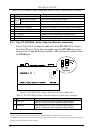
If necessary, set the H SYNC and V SYNC switches
1
, on the
underside
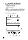
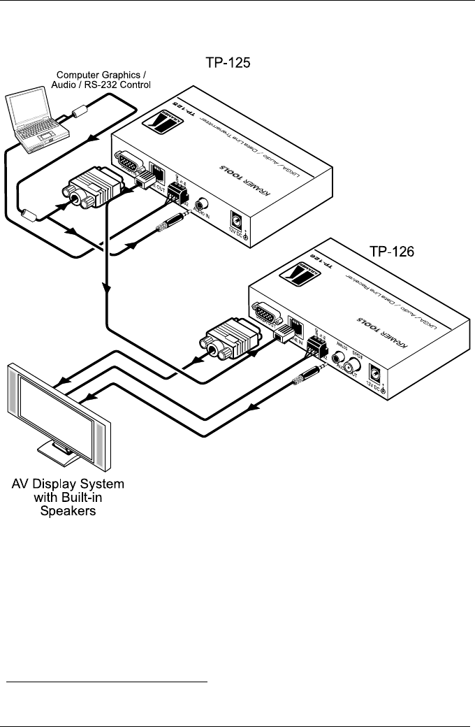
Figure 5: Connecting the UXGA / Audio / Data Line Transmitter / Receiver System
1 By default, both switches are set down (for negative V SYNC and H SYNC polarity)